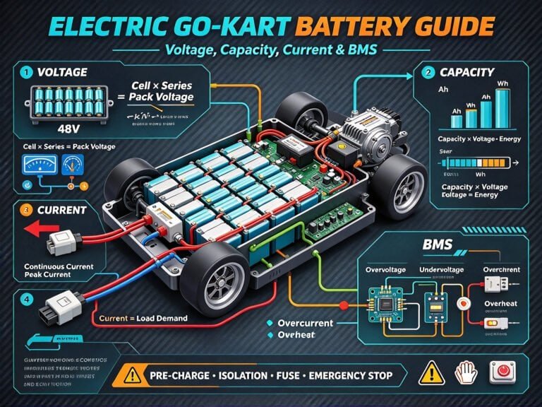
Battery Management System (BMS) Guide for OEM Engineers

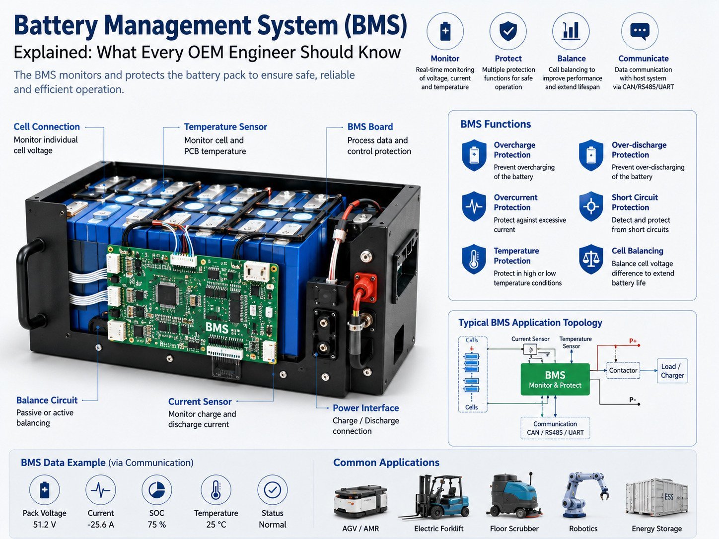
A Battery Management System (BMS) is an electronic control system used to monitor and manage rechargeable battery packs. For lithium battery packs, the BMS can monitor cell voltage, pack voltage, current, temperature, state of charge, and fault conditions. Depending on the design, it can also provide protection functions, cell balancing, data communication, and battery status information.

For OEM equipment manufacturers, BMS selection should not be based only on battery voltage and capacity. The BMS needs to correspond with the battery cells, pack configuration, charger, equipment controller, operating current, temperature range, communication requirements, and application environment.

This is particularly relevant for equipment such as AGVs, AMRs, robots, electric forklifts, floor cleaning machines, marine equipment, medical devices, e-bikes, and other battery-powered systems.

This guide explains the main functions of a BMS, how it works, and what OEM engineers should consider when developing or selecting a lithium battery pack.

Battery Management System BMS

What Is a Battery Management System (BMS)?

A Battery Management System, commonly known as a BMS, is an electronic system designed to monitor and manage a rechargeable battery pack.

A typical lithium battery BMS can monitor:

  • Individual cell voltage
  • Total battery voltage
  • 充電電流
  • 放電電流
  • Cell temperature
  • Battery pack temperature
  • 充電状態(SOC)
  • 健康状態(SOH)
  • Fault conditions

Depending on the BMS architecture, it may also provide:

  • 過充電保護
  • 過放電保護
  • 過電流保護
  • 短絡保護
  • 過熱保護
  • 低温保護
  • セルバランシング
  • Communication with external equipment

In an OEM battery pack, the BMS works together with the battery cells, protection components, enclosure, charger, and equipment controller.


Why Is a BMS Important for OEM Battery Packs?

OEM equipment can have different electrical loads, operating cycles, environmental conditions, and control systems. As a result, a battery pack cannot be fully specified by voltage and capacity alone.

For example, an equipment manufacturer may require a battery with:

  • 48V nominal voltage
  • 100Ah capacity
  • 100A continuous discharge current
  • 150A peak discharge current
  • CAN通信
  • 温度モニタリング
  • Low-temperature charging protection

A specification such as 48V 100Ah does not define all the requirements for the battery system.

The BMS needs to correspond with the battery cells, series configuration, current requirements, charger, controller, and communication system.

For this reason, BMS requirements are best considered during the equipment and battery development stage.


What Are the Main Functions of a BMS?

1. Cell Voltage Monitoring

Lithium battery packs are made by connecting multiple cells in series and parallel.

During charging and discharging, individual cells may show differences in voltage because of variations in cell characteristics, temperature, state of charge, and operating conditions.

A BMS can monitor the voltage of individual cells and detect conditions outside the configured operating range.

Cell voltage monitoring can support:

  • 過充電保護
  • 過放電保護
  • Cell voltage fault detection
  • Battery status monitoring
  • セルバランシング

The number of cells connected in series must correspond to the BMS design.


2. Pack Voltage Monitoring

In addition to individual cell voltage, the BMS monitors the total battery voltage.

Pack voltage information can be used for:

  • Battery status monitoring
  • SOC estimation
  • Charging control
  • Discharge monitoring
  • 故障検出
  • Communication with the equipment controller

The total battery voltage depends on the number of cells connected in series and the cell chemistry.

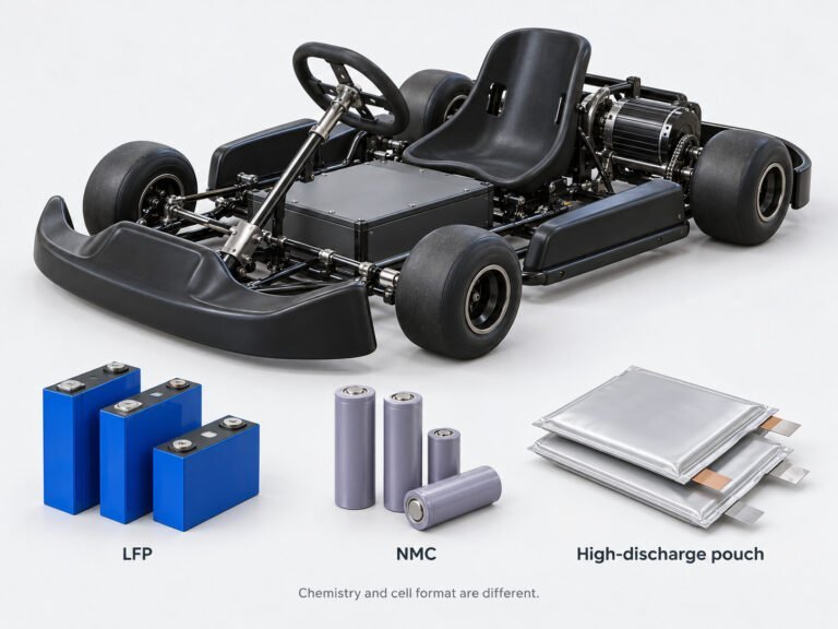
For example, a LiFePO4 battery and an NMC battery have different cell voltage characteristics, so the BMS parameters need to correspond to the selected chemistry.


3. Current Monitoring

A BMS can monitor the charging and discharge current of a battery pack.

Common current measurement methods include:

  • Shunt resistors
  • Hall-effect current sensors

Current information can be used for:

  • 過電流保護
  • Short-circuit detection
  • SOC estimation
  • Power calculation
  • Charge/discharge status
  • Fault diagnosis

For equipment such as electric forklifts, AGVs, AMRs, and industrial vehicles, current requirements should be evaluated based on actual load conditions.


4. Temperature Monitoring

Temperature is an important parameter in lithium battery management.

A BMS may monitor:

  • Cell temperature
  • Battery pack temperature
  • MOSFET temperature
  • Other critical component temperatures

NTC temperature sensors are commonly used for battery temperature measurement.

Temperature information can be used to control charging and discharging according to predefined parameters.

For example, some lithium battery systems restrict charging at low temperatures. High temperatures may also result in current limitations or protection actions depending on the BMS configuration.

Sensor location is also relevant. During PACK development, engineers should consider where temperature sensors need to be positioned to provide useful measurements.


5. Overcharge Protection

Lithium batteries have defined charging voltage ranges.

If a cell or battery pack reaches a configured voltage threshold, the BMS can take protective action according to the system design.

Overcharge protection parameters depend on:

  • 電池の化学組成
  • Cell specification
  • Series configuration
  • Charger output
  • BMS design

LiFePO4 and NMC batteries have different voltage characteristics, so their BMS parameters should not be treated as interchangeable.


6. Over-Discharge Protection

During battery discharge, cell voltage gradually decreases.

If the voltage reaches the configured lower limit, the BMS can restrict or stop discharge according to its protection strategy.

Over-discharge protection helps prevent the battery from continuing to operate outside its specified voltage range.

For equipment that remains unused for extended periods, OEM engineers should also consider BMS standby consumption and battery storage conditions.


7. Overcurrent Protection

Battery current can increase significantly during equipment startup, acceleration, lifting, climbing, or other high-load conditions.

A BMS may use different current parameters for:

  • 連続放電電流
  • ピーク放電電流
  • Peak current duration
  • 充電電流
  • 過電流保護

For example, if equipment normally operates at 80A but reaches 120A for a short period during startup, the BMS needs to account for both conditions.

Actual current measurements from the equipment can help engineers configure the BMS appropriately.


8. Short-Circuit Protection

A short circuit can result in a rapid increase in current.

Depending on its architecture, the BMS can detect abnormal current conditions and disconnect or restrict the current path.

However, short-circuit protection should not be considered a BMS-only function.

The complete battery pack may also require:

  • Fuses
  • Contactors
  • MOSFET
  • Busbars
  • Cables
  • Connectors
  • Insulation
  • Mechanical protection

Short-circuit protection should therefore be considered at the complete PACK system level.


9. Cell Balancing

Cells connected in series can develop differences in voltage and state of charge over time.

Cell balancing is used to manage some of these differences.

There are two common approaches.

Passive Balancing

Passive balancing typically uses resistors to dissipate a small amount of energy from selected cells.

This approach has a relatively simple circuit structure and is used in many battery management systems.

Active Balancing

Active balancing transfers energy between cells instead of primarily dissipating it as heat.

The circuit design is more complex, and the appropriate approach depends on factors such as battery capacity, cell count, application requirements, and BMS architecture.

OEM engineers should confirm the balancing method and balancing current when selecting a BMS.


What Are SOC and SOH?

充電状態(SOC)

SOC describes the estimated charge level of a battery.

A simplified concept is:

SOC = Available Charge / Reference Battery Capacity × 100%

However, SOC is not necessarily determined accurately by voltage alone.

A BMS may use a combination of:

  • 電圧
  • 現在
  • Coulomb counting
  • 温度
  • Battery models
  • Historical operating data

The SOC calculation method can vary between BMS designs.


健康状態(SOH)

SOH describes the condition of a battery relative to a defined reference condition.

Depending on the BMS, SOH calculations may consider:

  • Capacity degradation
  • 内部抵抗
  • Charge and discharge history
  • Battery usage
  • Other battery parameters

Different BMS manufacturers may use different algorithms to calculate SOH.

If an OEM controller needs to read SOH data, the calculation method and communication definition should be confirmed during system development.


BMS Communication Protocols

Modern battery-powered equipment may require communication between the battery and the equipment controller.

Common communication interfaces include:

CAN

CAN is widely used in:

  • 無人搬送車
  • AMR
  • 電動フォークリフト
  • 産業用車両
  • ロボット
  • Floor cleaning machines
  • Other industrial equipment

A BMS using CAN can transmit information such as:

  • 電圧
  • 現在
  • SOC
  • 温度
  • Fault status
  • Charging status

The exact CAN message structure needs to be defined according to the equipment control system.

RS485

RS485 is also used in industrial battery systems.

It can be combined with communication protocols such as Modbus RTU, depending on the application.

UART

UART can be used for communication between the BMS and external controllers or for configuration and debugging.

CAN FD

CAN FD provides a higher data capacity than classical CAN and can be considered when the equipment communication architecture supports it.

The communication interface should be selected based on the actual controller requirements rather than simply choosing a protocol based on its availability.


What Is a Smart BMS?

A basic BMS may focus on voltage, current, temperature monitoring, and protection.

A smart BMS can provide additional functions such as:

  • SOC reporting
  • SOH reporting
  • データロギング
  • Fault records
  • コミュニケーション
  • Parameter configuration
  • Battery status monitoring
  • Remote data access, depending on the system

For equipment such as AGVs, AMRs, robots, industrial vehicles, and cleaning machines, communication can allow the equipment controller to receive battery information.

However, not every application requires a smart BMS. The required functions should be determined by the equipment architecture.


How to Select a BMS for an OEM Battery Pack

OEM engineers should evaluate several parameters when selecting a BMS.

パラメータ What to Check
電池の化学組成 LiFePO4, NMC, Li-ion, etc.
Series configuration Number of cells in series
公称電圧 Battery system voltage
定員 Ah
連続放電電流 A
ピーク放電電流 A
充電電流 A
温度モニタリング Sensor quantity and location
セルバランシング Passive or active
コミュニケーション CAN, RS485, UART, etc.
Protection functions Voltage, current, temperature
動作温度 Application range
寸法 Available PACK space
Software parameters Equipment-specific requirements

The BMS should be evaluated as part of the complete battery system.


How Does a BMS Match the Battery Cells?

A BMS cannot be selected independently from the battery cells.

For example, if the battery pack uses LiFePO4 cells, the BMS needs to correspond to the LiFePO4 cell voltage range, series configuration, charging parameters, discharge requirements, and temperature limits.

If the battery uses NMC cells, the corresponding BMS parameters need to be configured according to the NMC cell specifications.

The basic relationship is:

Battery Cells → BMS → Charger → Controller → Equipment

These components need to work within compatible electrical and control parameters.


How Does the BMS Work with the Charger?

The charger and BMS have different functions.

The charger provides the required charging voltage and current, while the BMS monitors battery conditions and provides protection or control functions according to the battery system design.

OEM engineers should confirm:

  • 充電電圧
  • Maximum charging current
  • Charging profile
  • BMS charging limits
  • Charging connector
  • 通信要件
  • Charging temperature limits

If the charger and BMS communicate with each other, the communication protocol and data definitions should be confirmed during development.


Common BMS Design Issues in OEM Projects

Selecting a BMS Only Based on Battery Capacity

例えば、こうだ:

“The battery is 48V 100Ah, so we need a 100A BMS.”

This approach does not provide enough information.

BMS current specifications should be based on actual charging and discharge requirements, cell capability, protection requirements, and operating conditions.

Battery capacity and BMS current rating are different parameters.

Ignoring Peak Current

Equipment may have moderate average power consumption but higher short-term current during:

  • Motor startup
  • 加速
  • Lifting
  • Climbing
  • High-load operation

Peak current should therefore be measured or estimated during the equipment design process.

Ignoring Low-Temperature Charging

Outdoor equipment may operate in cold environments.

If the battery needs to be charged at low temperatures, the allowable charging temperature range should be considered during battery development.

The BMS can be configured to restrict charging when the measured temperature falls outside the specified range, depending on the battery design.

Defining Communication Too Late

If the equipment controller requires CAN communication, the communication specification should ideally be defined before battery development is completed.

Relevant information may include:

  • CAN ID
  • Data length
  • Signal definition
  • SOC format
  • Voltage data
  • Current data
  • Temperature data
  • Fault codes

Defining these requirements early can reduce integration work during prototype testing.


BMS Development Process for OEM Battery Packs

A typical OEM BMS development process can include the following stages.

Step 1: Define Equipment Requirements

Collect:

  • バッテリー電圧
  • 定員
  • Continuous current
  • Peak current
  • 稼働時間
  • 動作温度
  • Charger specifications
  • コントローラの仕様
  • 通信要件

Step 2: Select Battery Cells

Cell selection can consider:

  • 化学
  • 定員
  • 放電電流
  • 温度範囲
  • PACK dimensions
  • Expected operating cycle

Step 3: Select the BMS

The BMS should correspond to:

  • Cell series count
  • 充電電流
  • 放電電流
  • 温度モニタリング
  • Protection requirements
  • 通信要件

Step 4: Configure BMS Parameters

Parameters may include:

  • 過充電保護
  • 過放電保護
  • 過電流保護
  • 温度保護
  • セルバランシング
  • SOC calculation
  • Communication settings

Step 5: Integrate the Battery PACK

The battery cells, BMS, enclosure, connectors, cables, busbars, and protection components are integrated into the battery pack.

Step 6: Test the Battery

Testing can include:

  • キャパシティ・テスト
  • 充放電テスト
  • BMS protection testing
  • 温度試験
  • 通信テスト
  • 振動試験
  • エージング試験
  • Application testing

How Should a BMS Be Tested?

BMS testing should cover normal operating conditions as well as defined abnormal conditions.

Voltage Testing

Tests may verify:

  • 過充電保護
  • 過放電保護
  • Cell voltage monitoring
  • Cell voltage fault detection

Current Testing

Tests may evaluate:

  • Charging overcurrent
  • Discharge overcurrent
  • 短絡保護
  • Continuous current behavior

Temperature Testing

Testing can verify:

  • High-temperature protection
  • 低温保護
  • Low-temperature charging restrictions

Communication Testing

For a communication-enabled BMS, testing can verify:

  • CAN data
  • RS485 data
  • SOC
  • 電圧
  • 現在
  • 温度
  • Fault codes

Application Testing

Installing the battery in the actual equipment allows engineers to evaluate BMS behavior under representative operating conditions.

For example, an AGV battery can be tested during driving, acceleration, stopping, charging, and standby operation.


BMS and Lithium Battery Safety

A BMS is one part of lithium battery safety design. It should not be treated as the only safety measure.

A complete battery safety design can involve:

  • 細胞の選択
  • 細胞の一貫性
  • PACK structure
  • Electrical insulation
  • Fuses
  • Contactors
  • Connectors
  • Cables
  • 熱管理
  • Enclosure
  • ビーエムエス
  • 充電器
  • Manufacturing processes
  • Testing procedures

For OEM battery projects, these elements should be considered together.


How to Develop a Custom BMS for OEM Equipment

When developing a custom battery pack, OEM engineers should provide detailed equipment information.

Electrical Requirements

  • Operating voltage
  • モーター出力
  • Maximum current
  • Peak current
  • Required runtime
  • 充電電圧
  • 充電電流

Mechanical Requirements

  • バッテリー寸法
  • 設置位置
  • Mounting method
  • コネクタの種類
  • Cable length
  • Cable routing

Software Requirements

  • 通信プロトコル
  • CAN ID
  • Data format
  • SOC requirements
  • Fault codes
  • Controller logic

Environmental Requirements

  • 動作温度
  • 充電温度
  • Humidity
  • 振動
  • Dust and water exposure

This information gives the battery engineering team a basis for selecting the cells, BMS, electrical protection, and PACK structure.


Certifications and Compliance Considerations

BMS design is only one part of battery compliance.

Requirements can vary depending on the battery chemistry, application, transportation method, and destination market.

Depending on the project, OEM manufacturers may need to evaluate:

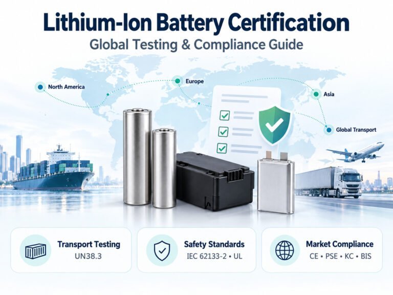
  • UN 38.3 transportation testing
  • Applicable IEC standards
  • Regional safety requirements
  • Electromagnetic compatibility requirements
  • Environmental requirements
  • Applicable equipment regulations

For batteries placed on the European market, applicable requirements under EU電池規則(EU)2023/1542 should be evaluated according to the battery category and intended use.

Compliance requirements should be identified during product development rather than being considered only after the battery design is completed.


Frequently Asked Questions

What is a Battery Management System?

A Battery Management System is an electronic system used to monitor and manage a rechargeable battery pack. It can monitor voltage, current, temperature, SOC, and fault conditions and can provide protection functions according to its design.

Do lithium batteries need a BMS?

Multi-cell lithium battery packs generally require an appropriate battery management and protection system. The specific BMS architecture depends on the battery design and application.

Can a BMS extend battery life?

A BMS can help manage battery operation within specified voltage, current, and temperature limits. However, battery service life also depends on cell characteristics, charging conditions, operating temperature, depth of discharge, usage frequency, and other factors.

Can a BMS control a charger?

Some battery systems allow the BMS to communicate with or control the charging process. Other systems use electrical protection components to manage the charging circuit. The exact architecture depends on the battery and charger design.

Does every BMS need CAN communication?

No. CAN communication is not required for every battery. If the equipment controller needs battery data such as SOC, voltage, current, temperature, or fault information, CAN or another suitable communication interface can be considered.

Can the same BMS be used for LiFePO4 and NMC batteries?

A BMS should not be assumed to be directly interchangeable between LiFePO4 and NMC batteries. Voltage limits, charging parameters, protection settings, and other parameters need to correspond to the battery chemistry and cell configuration.

When should an OEM engineer define the BMS?

BMS requirements should ideally be defined during the battery and equipment development stage, together with the battery cells, charger, controller, current requirements, and communication protocol.


結論

A Battery Management System is an important component of a lithium battery pack, but its role extends beyond basic battery protection. A BMS can monitor cell voltage, pack voltage, current, temperature, SOC, SOH, and fault conditions. Depending on the design, it can also support cell balancing, communication, and application-specific protection functions.

For OEM engineers, BMS selection should be based on the complete equipment requirements rather than battery capacity alone. Cell chemistry, series configuration, charging current, continuous and peak discharge current, temperature range, communication protocol, installation space, and operating environment should all be considered.

For applications such as AGVs, AMRs, robots, electric forklifts, floor scrubbers, marine equipment, medical devices, e-bikes, and industrial equipment, the BMS should be developed and tested as part of the complete battery system.

A structured development process can include cell selection, BMS selection, parameter configuration, PACK integration, prototype testing, communication testing, and application validation.

By defining BMS requirements early in the OEM development process, engineers can address battery monitoring, protection, communication, and system integration requirements as part of the overall product design.

Learn how a Battery Management System (BMS) works, including voltage, current and temperature monitoring, battery protection, cell balancing, SOC, communication, and OEM battery pack design.
2026-08-21
+
Learn how to select lithium batteries for Electric Scissor Lifts based on voltage, capacity, discharge current, BMS, charging, dimensions, and operating conditions.
2026-08-21
+
Learn how to choose a battery for inspection robots based on voltage, capacity, discharge current, battery chemistry, BMS, charging, size, and operating temperature.
2026-08-20
+
Learn how to choose the right lawn tractor battery based on voltage, CCA, capacity, size, terminals, battery chemistry, and charging requirements.
2026-08-20
+