
A battery management system, or BMS, monitors battery conditions and controls the functions included in its design.
For equipment manufacturers, BMS customization may involve protection settings, communication, sleep modes, fault records and charging coordination. The available functions depend on the hardware, firmware and battery construction.
This guide explains what OEMs can specify and what needs to be verified before production.
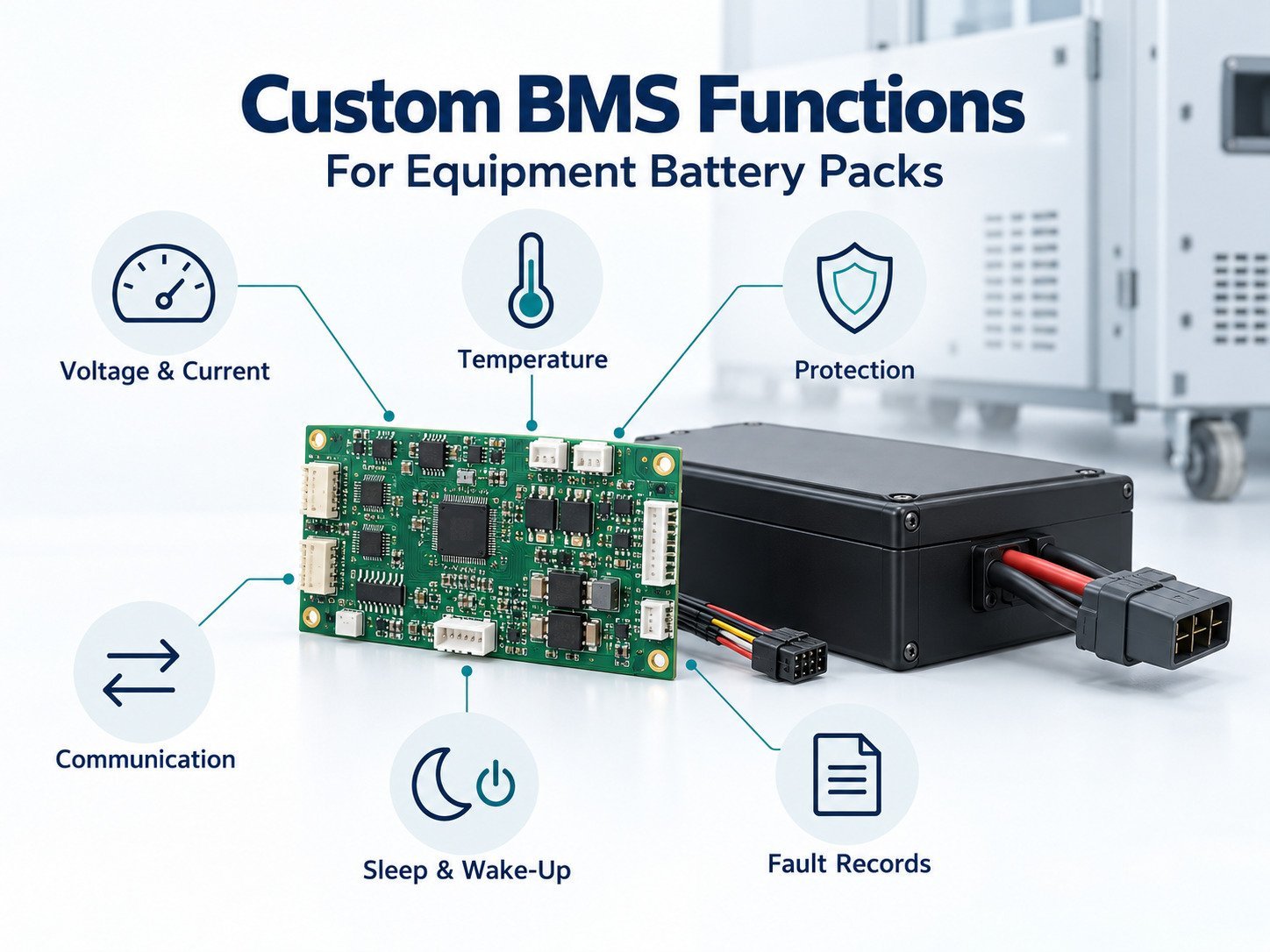
1. Separate Hardware Capabilities From Software Settings
Some requests can be handled through configuration. Others require hardware changes.
For example, changing a supported reporting interval may involve firmware settings. Adding a current sensor, communication transceiver or switching circuit may require a board revision.
| Customization Type | 예제 |
|---|---|
| 구성 | Supported thresholds, delays and reporting intervals |
| Firmware | Messages, operating states and event handling |
| Hardware | Sensors, interfaces, switching devices and memory |
| Pack integration | Sensor placement, wiring and thermal arrangement |
Confirm feasibility before treating a requested function as included.
2. Voltage Monitoring
A BMS can measure pack voltage and the voltages of series-connected cells or parallel groups.
Specify:
- Measurement points.
- Operating range.
- Required accuracy under defined conditions.
- Sampling and reporting intervals.
- Fault detection.
- Response to invalid readings.
In a series–parallel pack, measuring a parallel group does not necessarily provide individual data for every cell within that group.
Document what the reported value represents.
3. Current Measurement
Current measurement may support protection, energy tracking and state estimation.
Define:
- Charge and discharge measurement range.
- Current direction convention.
- Accuracy requirements.
- Zero-current offset requirements.
- Sampling and reporting intervals.
- Transient capture requirements.
A displayed current value and a protection circuit may use different measurement paths or timing.
Confirm which data is available to the host and which functions operate locally.
4. 온도 모니터링
Temperature sensors can be assigned to cells, switching components or other specified locations.
The design should identify:
- Sensor type and quantity.
- Placement.
- Measurement range.
- Accuracy requirements.
- Open-circuit or short-circuit detection.
- Operating restrictions.
- Recovery behavior.
A sensor reports conditions at its location. It does not establish the temperature of every cell.
Validate placement within the intended enclosure and equipment installation.
5. Protection Functions
Depending on the architecture, protection may address:
- Cell overvoltage.
- Cell undervoltage.
- Charge overcurrent.
- Discharge overcurrent.
- Short circuit.
- Charging temperature.
- Discharging temperature.
For each function, specify the trigger, delay, action and recovery condition.
Protection settings must follow the approved cell, component and system limits. They are not unrestricted user preferences.
Distinguish Warnings From Disconnection
A warning can request action from the equipment. Protective disconnection interrupts a power path.
Define which conditions produce:
- A status message.
- An operating restriction.
- A controlled shutdown request.
- Charge or discharge disconnection.
The equipment must have a defined response to each action.
6. State-of-Charge Reporting
State of charge, or SOC, is an estimate of battery charge condition.
A custom implementation may provide a percentage, remaining capacity or another defined output.
Specify:
- Reporting format.
- Reference capacity.
- Initialization.
- Update behavior.
- Calibration or learning requirements.
- Behavior after storage.
- Response to invalid estimates.
Do not treat SOC as a direct measurement of remaining equipment runtime.
Runtime also depends on load, temperature, operating limits and battery condition.
7. State-of-Health Information
State of health, or SOH, needs a defined meaning.
It may refer to estimated capacity retention, resistance or another documented indicator.
If SOH is requested, define:
- The reported parameter.
- Calculation method.
- Required operating data.
- Update conditions.
- Validation method.
- Conditions in which the estimate is unavailable.
A BMS should not report an unsupported percentage merely because the host has a field labeled “SOH.”
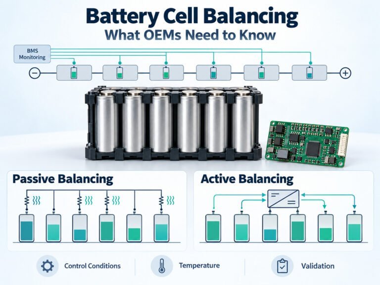
8. Cell Balancing
Balancing manages charge distribution among series-connected cells or groups.
The implementation may use passive discharge paths or an active transfer circuit.
Specify:
- Balancing method.
- Activation conditions.
- Current.
- Operating duration.
- Channel scheduling.
- Temperature limits.
- Stop conditions.
- Status reporting.
Balancing does not repair a damaged cell or replace protection.
Its operation should be evaluated alongside the charging schedule and battery configuration.
9. Equipment Communication
A BMS may communicate through CAN, RS485, SMBus, UART or another supported interface.
The interface name alone does not establish compatibility.
Provide the host protocol and define:
- Messages or register addresses.
- Data units and scaling.
- Byte order.
- Transmission intervals.
- Timeouts.
- Fault meanings.
- Command permissions.
- Version handling.
Validate the BMS with the actual controller, charger or display.
10. Sleep and Wake-Up Functions
Sleep functions can be used to manage battery electronics during idle periods.
Define:
- Entry conditions.
- Active circuits during sleep.
- Expected consumption under stated conditions.
- Wake-up sources.
- Wake-up timing.
- Communication behavior after waking.
- Response if waking fails.
Wake-up may involve a button, charger, communication signal or another designed input.
Do not assume a sleeping battery has zero consumption.
11. Charging Coordination
The BMS may communicate charging permission or limits to a compatible charger.
Functions can include:
- Charge enable.
- Current-limit reporting.
- Temperature restrictions.
- Fault reporting.
- Charge termination coordination.
Define which device controls each action.
The charger must match the approved battery design. BMS protection should not be treated as the normal charging termination method.
12. Precharge and Power Switching
Some equipment requires controlled connection to its input capacitance.
Where supported, the BMS may participate in precharge or contactor control.
Document:
- Connection sequence.
- Completion criteria.
- Timeout.
- Switch feedback.
- Fault response.
- Repeated-start behavior.
These functions require suitable hardware and system validation. They cannot be added through firmware alone if the necessary circuit is absent.
13. Fault Records and Service Data
Event records can support fault investigation.
Specify which information is stored:
- Event code.
- Voltage.
- Current.
- Temperature.
- Operating state.
- Event count.
- Timestamp or relative time.
- Hardware and firmware version.
Also define memory capacity, overwrite behavior, retention and access.
A timestamp requires a defined time source. Do not assume the BMS knows calendar time.
14. Configuration and Firmware Access
If field configuration or firmware updates are permitted, define who can perform them and how access is controlled.
Document:
- Read and write permissions.
- Parameter limits.
- Version identification.
- Update conditions.
- Interruption recovery.
- Verification after update.
- Service records.
Changes affecting protection or operating behavior should follow the approved review process.
15. Define Communication-Loss Behavior
The battery and host need a response when messages stop or become invalid.
Depending on the application, the design may continue within defined limits, restrict operation or request shutdown.
The response should follow the system requirements and hazard assessment.
Essential local protection must function according to the battery design without depending solely on host communication.
16. Validate Custom Functions
Prepare test conditions and acceptance criteria for each requested function.
| 함수 | Verification |
|---|---|
| Measurements | Defined accuracy and timing |
| 보호 | Trigger, delay, action and recovery |
| SOC | Behavior across the intended duty cycle |
| Balancing | Activation, current and thermal behavior |
| 커뮤니케이션 | Data interpretation and fault handling |
| Sleep | Consumption, entry and wake-up |
| 충전 | Battery–charger interaction |
| Logging | Record content and retrieval |
| Updates | Permissions, interruption and recovery |
Use approved test procedures. Do not bypass protection or create hazardous battery conditions outside a controlled test process.
OEM BMS Requirements Checklist
Before requesting customization, provide:
- Cell model and battery configuration.
- Voltage and current requirements.
- Operating temperature conditions.
- Equipment duty cycle.
- Charger information.
- Host protocol.
- Sleep and wake-up requirements.
- Fault-response requirements.
- Required service data.
- Update and access rules.
- Validation responsibilities.
Identify mandatory functions and unresolved requests.
자주 묻는 질문
Can Every BMS Function Be Customized Through Software?
No. Some functions require sensors, interfaces, memory or switching hardware.
Does Communication Support Mean Host Compatibility?
No. Messages, units, timing and operating behavior must also match.
Can Protection Thresholds Be Changed?
Only within the approved design and review process.
Can the BMS Predict Equipment Runtime?
A runtime estimate requires a defined load model and validation. SOC alone does not establish runtime.
What Should Be Controlled During Production?
Control the hardware revision, firmware, parameter set, programming procedure and acceptance tests.
Preparing a Custom BMS Specification
Define the required behavior before choosing features.
Identify what the BMS measures, what it controls and what the host must do. Record the limits, interfaces and fault responses, then validate the approved implementation in the intended equipment.
 English
 Chinese
 Japanese
 German
 French
 Korean

