
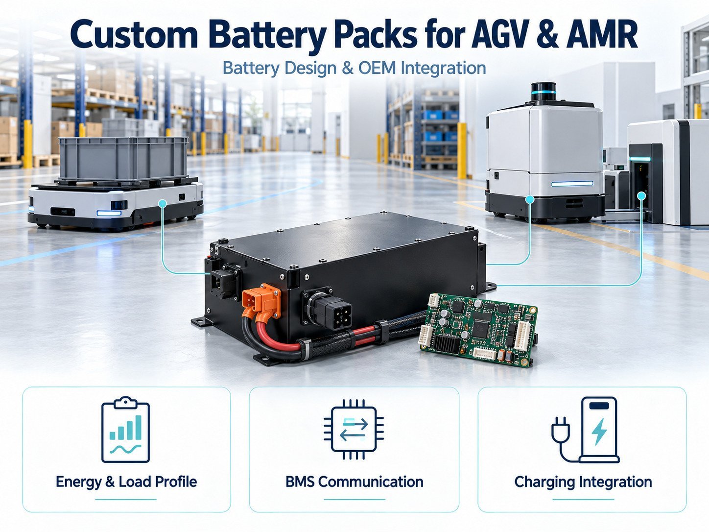
A battery pack affects a mobile robot’s operating time, charging schedule, payload allocation and maintenance procedures. For automated guided vehicles (AGVs) and autonomous mobile robots (AMRs), battery selection should therefore be part of system design.
Specifying voltage and capacity is only one step. OEMs also need to define load profiles, charging conditions, communication requirements, enclosure dimensions and fault responses.
This guide explains the information needed to develop and validate a custom lithium battery pack for AGV and AMR applications.
The guidance below supports project planning. Final specifications require validation against the robot design, operating conditions and applicable standards.
1. Start With the Robot’s Duty Cycle
AGV and AMR battery requirements should be based on the actual operating cycle.
A robot may alternate between driving, lifting, waiting, processing sensor data and charging. Each activity places a different demand on the battery.
Before selecting cells, document:
- Operating hours per shift.
- Payload and travel conditions.
- Acceleration and stopping patterns.
- Lift or actuator operation.
- Idle and standby consumption.
- Available charging periods.
- Ambient temperature.
- Required reserve energy.
Use measurements from a prototype or representative system where available. Motor ratings alone do not describe the robot’s total energy consumption.
2. Define Voltage Across the Operating Range
A nominal voltage such as 24V or 48V does not describe the complete battery operating range.
The OEM should specify the voltage limits accepted by the motor controller, charger, DC-DC converters and auxiliary electronics.
| 매개변수 | Information to Confirm |
|---|---|
| 공칭 전압 | Intended system voltage |
| Full-charge voltage | Compatibility with connected equipment |
| Discharge endpoint | Required shutdown and reserve behavior |
| Voltage under load | Operation during current peaks |
| Regenerative voltage | Behavior when the drive returns energy |
Cell chemistry and series configuration determine the pack’s voltage characteristics.
Do not assume that two packs with the same nominal voltage have interchangeable charging requirements.
3. Calculate Energy Capacity From the Mission
Capacity in ampere-hours should be considered alongside energy in watt-hours.
For preliminary planning:
Nominal energy (Wh) = nominal voltage (V) × capacity (Ah)
For example, a nominal 48V, 40Ah pack contains approximately 1,920Wh of nominal energy. This figure does not establish usable energy under every operating condition.
A mission requiring an average battery output of 300W for four hours would consume approximately 1,200Wh. Pack sizing must also account for:
- The permitted state-of-charge window.
- Temperature-related limits.
- Capacity loss over the service period.
- Peak-load behavior.
- Energy needed to reach a charging station.
- System losses not included in the measured load.
These figures are calculation examples, not product recommendations.
4. Specify Continuous and Peak Current
A battery must support the robot’s current demand during normal operation and defined transient events.
Continuous current and peak current should be specified separately.
For each peak, document its magnitude, duration and repetition rate. Starting a motor, lifting a load or operating several actuators together may create different current profiles.
The current path includes cells, interconnects, protection devices, connectors and cables. A cell’s discharge rating does not establish the rating of the complete pack.
For preliminary calculations:
Current (A) ≈ electrical power (W) ÷ battery voltage (V)
Use measured waveforms to validate transient behavior and voltage drop.
5. Select Cell Chemistry for the Application
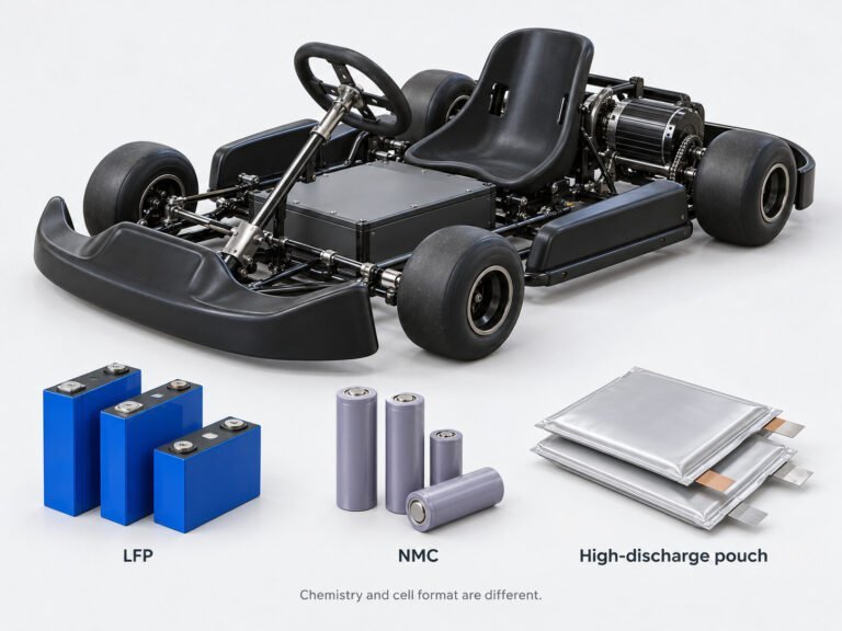
Custom robotics packs may use lithium iron phosphate (LFP) or other lithium-ion chemistries, including nickel-based formulations.
Chemistry selection should consider:
- Available installation space.
- Allowed battery mass.
- Voltage requirements.
- Charging schedule.
- Operating temperature.
- Required service life.
- Cell availability.
- Product safety requirements.
Chemistry names alone do not establish pack performance. Evaluate the selected cell’s data sheet and test results under the intended duty cycle.
Cycle-life claims should include test conditions such as depth of discharge, temperature, charge rate and capacity retention endpoint.
6. Define BMS Functions and Fault Responses
The battery management system monitors operating conditions and controls specified protection functions.
Depending on the design, these functions may include cell voltage monitoring, current measurement, temperature monitoring and protection against overvoltage, undervoltage, overcurrent and short circuits. Source: Texas Instruments Battery Protection Overview
For an AGV or AMR, the OEM and battery supplier should agree on:
- Protection thresholds and delays.
- Charge and discharge permissions.
- Temperature-dependent operating limits.
- Fault recovery conditions.
- Cell balancing behavior.
- Sleep and wake-up logic.
- Event recording.
- Response to communication loss.
A protection trip can interrupt robot movement. The system design should therefore distinguish operating warnings, controlled shutdown requests and protective disconnection.
Essential local protection should remain functional when host communication is unavailable.
7. Specify Battery Communication
Battery communication connects the BMS with the robot controller, charger or maintenance system.
Possible interfaces include CAN, RS485, SMBus and UART. Selection should follow the host requirements and installation conditions.
The interface name alone does not establish compatibility. The protocol document should define:
- Message identifiers or register addresses.
- Data units and scaling.
- Byte order.
- Update intervals.
- Timeout thresholds.
- Fault meanings.
- Command permissions.
- Protocol version.
For robotics applications, useful data may include pack voltage, current, temperature, state of charge, charging limits and fault status.
State of charge is an estimate. Its behavior depends on the gauging method, cell characteristics, operating history and conditions. Validate it under the robot’s duty cycle. Source: Texas Instruments Battery Fuel Gauges
Define Low-Energy Behavior
Agree on how the robot uses battery information to:
- Request charging.
- Finish or reject a task.
- Maintain energy for travel to a dock.
- Enter a controlled shutdown.
- Identify stale or unavailable data.
A displayed state-of-charge percentage should not be the only input used to define protection behavior.
8. Coordinate the Battery and Charging System
Charging requirements should be established together with the battery design.
| Charging Approach | Design Questions |
|---|---|
| Scheduled charging | Is the available charging period sufficient for the next shift? |
| 기회 충전 | Can the pack accept the planned charge profile during short stops? |
| Automatic docking | How are alignment, contact engagement and charge permission verified? |
| 배터리 교체 | How are connection sequencing, identification and handling controlled? |
Specify charger voltage, current, termination behavior and temperature limits.
For automatic docking, assess exposed-contact protection, contact resistance, contamination and repeated connection cycles.
Charging time should be validated across the intended state-of-charge range and temperature conditions. It should not be calculated solely by dividing capacity by charger current.
9. Address Regenerative Braking and Inrush Current
Some robot drives return energy to the DC bus during braking or deceleration.
If regeneration is used, define the battery’s permitted charge current and the robot’s response when the pack cannot accept that energy—for example, near full charge or outside charging temperature limits.
The host also needs to account for what happens if the BMS disconnects during regeneration.
Separately, connecting a battery to a capacitive input can create inrush current. Determine whether the system requires precharge or another controlled connection method.
Document the sequence between connection, precharge, contactor operation and drive enable.
10. Plan Mechanical and Thermal Integration
A custom enclosure must fit the robot and support its operating conditions.
Provide the battery supplier with:
- Installation drawings and dimensional limits.
- Mounting points and orientation.
- Mass restrictions.
- Connector locations.
- Cable routing.
- Handling and service requirements.
- Vibration and shock conditions.
- Environmental exposure.
- Thermal conditions inside the robot.
Review accessible terminals, cable strain relief and protection against movement within the enclosure.
Where an ingress protection rating is specified, confirm that the assembled pack—including connectors and service openings—has been assessed for that requirement.
Evaluate Temperature in the Installed Position
Ambient temperature does not necessarily represent cell temperature.
Measure pack temperatures during representative driving, lifting and charging cycles. Include the effects of nearby motors, power electronics and restricted airflow.
11. Define Service Life and Maintenance
Battery service life depends on operating conditions and the endpoint used to define replacement.
Instead of specifying only “500 cycles,” document:
- Test temperature.
- Charge and discharge rates.
- Depth of discharge.
- Capacity retention endpoint.
- Calendar-life expectations.
- Allowed resistance increase.
- Required robot runtime at end of service.
Maintenance planning may include connector inspection, fault-log review and capacity checks.
Replacement packs should have documented electrical, mechanical and communication compatibility.
12. Review Safety Standards and Transport Requirements
Battery testing and complete robot safety assessment serve different purposes.
IEC 62619
IEC 62619 addresses industrial secondary lithium cells and batteries. Its stated scope includes motive applications such as AGVs, subject to the standard’s boundaries. Source: IEC 62619:2022
ISO 3691-4
ISO 3691-4 addresses driverless industrial trucks and their systems. Its examples include AGVs and AMRs.
It is a system-level safety standard, not a substitute for battery assessment. Confirm the applicable edition and product classification for the project. Source: ISO 3691-4:2023
UN38.3
Lithium battery transport requires assessment against applicable UN38.3 provisions and the relevant shipping rules. Manufacturers and distributors must provide applicable test summary information.
UN38.3 documentation does not replace product safety evaluation. Source: PHMSA Lithium Battery Test Summaries
Additional requirements depend on the destination market, robot classification and installation. Confirm the compliance plan before design freeze.
13. Validate the Pack in the Robot
Prototype testing should assess the battery, charger and robot together.
| Test Area | Verification |
|---|---|
| Mission runtime | Energy consumption under representative routes and payloads |
| Peak loads | Current, voltage drop and protection behavior |
| 충전 | Charge profile, temperature and dock operation |
| 커뮤니케이션 | Data interpretation, timing and timeout behavior |
| Power sequencing | Startup, precharge, shutdown and reconnection |
| Regeneration | DC-bus behavior when energy returns from the drive |
| Thermal operation | Cell and component temperatures |
| Mechanical integration | Mounting, cables, connectors and handling |
| Fault response | Controlled behavior during specified failures |
| 상태별 요금 추정 | Agreement with measured operation across the duty cycle |
Record hardware revisions, firmware versions, test conditions and acceptance criteria.
Passing a bench test does not establish performance in the installed robot.
14. Information to Include in an OEM Battery RFQ
A battery request for quotation should contain enough information to establish the design scope.
Include:
- Robot application and destination markets.
- Voltage range and energy requirement.
- Measured duty cycle.
- Continuous and peak current profiles.
- Charging method and charger specification.
- Regenerative charging conditions.
- BMS functions and communication document.
- Installation drawing and mass limit.
- Environmental and thermal conditions.
- Service-life test conditions.
- Compliance requirements.
- Prototype and production quantities.
- Validation responsibilities.
Ask the supplier to identify assumptions, exclusions and items requiring confirmation.
자주 묻는 질문
Can AGVs and AMRs Use the Same Battery Design?
They can when their electrical, mechanical, charging and communication requirements match. The AGV or AMR label alone does not determine the battery specification.
Is a 48V Battery Compatible With Every 48V Robot?
No. Full-charge voltage, discharge limits, connectors, current capability and communication requirements must also match.
Can an Existing Battery Be Adapted for Automatic Charging?
Possibly, but charger compatibility, connection sequencing, contacts, communication and thermal behavior require review.
Does CAN Support Establish Compatibility?
No. The battery and host must use compatible application messages and timing.
How Should Cycle Life Be Specified?
State the test conditions and replacement endpoint alongside the cycle count.
What Should Be Confirmed Before Production?
Confirm the approved design, firmware, protocol, manufacturing test plan, compliance documentation and system validation results.
Preparing an AGV or AMR Battery Project
Begin with the robot’s measured duty cycle and host requirements. Define the voltage range, usable energy, current profile, charging strategy and fault behavior.
Use these requirements to develop the pack specification, then validate the battery in the intended robot configuration before production.
 English
  Chinese
  Japanese
  German
  French
  Korean
