
A cleaning robot uses battery power for movement, cleaning mechanisms, navigation and control. Depending on the equipment, it may also power suction motors, pumps, valves, lighting and communication devices.
These loads change throughout a cleaning task. Battery design should therefore start with the operating sequence rather than nominal voltage and capacity alone.
This guide explains the requirements OEMs should document when developing a battery pack for a cleaning robot.
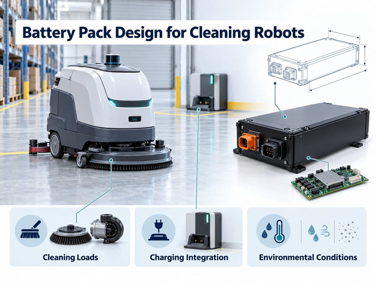
1. Define the Cleaning Application
A floor-scrubbing robot, vacuum robot and outdoor cleaning platform perform different tasks.
Document the intended application, including:
- Surface materials.
- Cleaning area and route.
- Operating duration.
- Travel speed.
- Brush or pad operation.
- Suction requirements.
- Pump and valve operation.
- Payload and fluid conditions.
- Charging schedule.
- Environmental exposure.
For equipment carrying water, define the operating conditions associated with tank fill levels.
Use measurements from a representative prototype where available. Record the robot configuration and task conditions with each result.
2. Build a Load Inventory
List every subsystem powered by the battery.
| Subsystem | Information to Record |
|---|---|
| 駆動モーター | Running current, acceleration and turning |
| Brush or pad motors | Startup, operating load and obstruction behavior |
| Suction system | Operating modes and activation periods |
| Pumps and valves | Duty cycle and switching events |
| Navigation sensors | Supply requirements and operating schedule |
| Computing hardware | Startup, processing and standby consumption |
| コミュニケーション | Transmission and idle activity |
| Auxiliary circuits | Lighting, fans and other fitted devices |
Identify which loads operate together.
A robot may drive, scrub and extract water simultaneously. The battery specification must represent that combined load.
3. Measure the Operating Profile
Cleaning conditions can affect electrical demand.
Record:
- Floor material.
- Surface condition.
- Brush or pad type.
- Applied cleaning pressure.
- Travel settings.
- Suction setting.
- Fluid load.
- Route gradients.
- Ambient temperature.
Measure battery-side voltage and current during the task.
Component nameplate ratings do not describe the complete operating profile. Separate measured values from estimates in the design records.
4. Specify the Voltage Range
The battery must match the input requirements of the connected electronics.
Define:
- Nominal voltage.
- Full-charge voltage.
- Normal discharge endpoint.
- Voltage behavior under transient loads.
- Controller undervoltage response.
- BMS protection thresholds.
Check the drive controllers, cleaning motor controllers, DC-DC converters and auxiliary devices.
A shared nominal voltage label does not establish compatibility across the operating range.
5. Calculate Task Energy
Divide the task into operating stages.
For each stage:
Energy (Wh) = average battery-side power (W) × duration (h)
The following table is an illustrative calculation.
| Stage | Average Battery-Side Power | 期間 | エネルギー |
|---|---|---|---|
| Travel and cleaning | 500W | 2 hours | 1,000Wh |
| Return travel | 180W | 0.2 hours | 36Wh |
| Waiting | 25W | 0.4 hours | 10Wh |
| Total | — | — | 1,046Wh |
These figures do not specify a particular robot.
Each stage should include all active loads. Do not add brush, suction or computing consumption again if it is already included in the battery-side measurement.
6. Define Usable Energy and Reserve
Calculated task energy does not automatically equal the required nominal battery energy.
Account for:
- The permitted operating window.
- Temperature conditions.
- Battery condition at the service endpoint.
- Travel to the charging station.
- Waiting and docking attempts.
- Required post-cleaning actions.
- Controlled shutdown.
Define the basis of each allowance. Avoid using an unexplained reserve percentage.
Nominal energy can be estimated from voltage and capacity, but usable energy requires verification under the specified conditions.
7. Document Startup and Transient Loads
Brush, suction and drive motors may start at different times or simultaneously.
For each event, record:
- Current magnitude.
- Duration.
- Repetition rate.
- Voltage response.
- Battery temperature.
- State of charge.
Specify how the equipment responds to a brush obstruction or motor fault.
Do not use the battery’s protective disconnection as the normal method of controlling a cleaning mechanism.
The current requirement applies to cells, BMS components, protective devices, interconnections, cables and connectors.
8. Coordinate BMS and Robot Controls
The BMS and robot controller need defined responsibilities.
The specification should cover:
- Voltage and temperature monitoring.
- Current limits.
- Charge and discharge permissions.
- Warnings.
- Protective disconnection.
- Fault recovery.
- Sleep and wake-up.
- Communication-loss behavior.
For example, a low-energy warning may initiate a controlled sequence that stops cleaning mechanisms and returns the robot to its dock.
The required sequence depends on the equipment. Document it rather than assuming that every function stops at the same time.
Essential local battery protection should operate according to the design when host communication is unavailable.
9. Specify Battery Communication
Where communication is required, obtain the host protocol before selecting the BMS.
Document:
- Interface type.
- Message identifiers or registers.
- Units and scaling.
- Byte order.
- Update intervals.
- Timeouts.
- Fault codes.
- Command permissions.
- Firmware versions.
Data may include voltage, current, temperature, state of charge and charging status.
State of charge is an estimate. Validate its use in task scheduling and return-to-dock decisions.
10. Integrate Automatic Charging
Automatic docking involves the battery, charger, contacts and robot controls.
Define:
- Dock alignment.
- Contact engagement.
- Connection verification.
- Charging permission.
- Power-contact energization.
- Charging voltage and current.
- Temperature limits.
- Termination behavior.
- Failed-docking response.
Evaluate contamination and moisture at the charging interface.
The presence of docking contacts does not establish that charging can begin safely in every contact condition. Use the approved connection and control sequence.
11. Review Moisture and Cleaning Exposure
Cleaning equipment may encounter liquid from operation, spills, tank leaks or maintenance.
Map possible exposure paths around:
- Tank joints.
- Pumps and hoses.
- Cable openings.
- Charging contacts.
- Battery access covers.
- Drainage paths.
Separate the robot’s cleaning function from the procedures used to clean the robot itself.
If an ingress protection rating is required, identify the assembled configuration and test conditions. Do not assume that a rating permits every washing method or chemical exposure.
Document the approved cleaning procedure.
12. Assess Thermal Conditions
Battery temperature depends on the installation as well as the environment.
レビュー
- Heat from motor controllers.
- Nearby motors.
- Enclosure airflow.
- Charging location.
- Fluid-system layout.
- Insulation and mounting materials.
Measure cell and component temperatures during representative cleaning and charging.
Ambient temperature alone does not establish internal battery temperature.
13. Define Mounting and Service Access
Provide drawings for the battery installation.
以下を含める:
- Dimensions and tolerances.
- Mounting points.
- Retention features.
- Connector locations.
- Cable routes.
- Removal path.
- Handling method.
- Mass requirements.
If the battery is removable, specify the connection and locking procedure.
Service access should not require uncontrolled contact with fluid systems, moving mechanisms or electrical terminals.
14. Include Standby and Storage
A cleaning robot may remain connected to its dock or wait between tasks.
Define:
- Circuits active during standby.
- Battery sleep conditions.
- Wake-up sources.
- Communication availability.
- Permitted charger connection.
- Storage procedure.
- Inspection requirements.
Do not assume that an idle robot consumes no energy.
Use model-specific instructions for storage charge condition and inspection intervals.
15. Establish Service-Life Requirements
A cycle-life statement requires test conditions.
Record:
- Charging profile.
- Discharge profile.
- Depth of discharge.
- Temperature.
- Rest periods.
- Capacity-retention endpoint.
Also account for calendar aging during storage and standby.
Define replacement according to the equipment’s requirements, such as task completion, usable energy or power delivery.
Do not present cell test results as verified life data for the assembled robot battery.
16. Validate the Battery in the Cleaning Robot
Set acceptance criteria before testing.
| Test Area | Verification |
|---|---|
| Task energy | Completion of the defined cleaning sequence |
| 現在 | Continuous and transient demand |
| Startup | Motor sequencing and voltage response |
| Fault handling | Response to defined motor and system faults |
| 充電 | Docking, control and termination |
| コミュニケーション | Data interpretation and timeout behavior |
| Thermal operation | Cell and component temperatures |
| Environmental exposure | Project-specific moisture and mechanical conditions |
| Shutdown | Cleaning stop, return and power-down sequence |
| Service | Removal, replacement and inspection |
Record floor conditions, cleaning settings, fluid load, software versions and battery configuration.
Bench operation alone does not establish behavior during an installed cleaning task.
17. Confirm Documentation Requirements
Identify requirements for the battery’s application, destination markets and transport arrangement.
Confirm that reports and certificates cover the supplied model and construction.
Battery documentation does not automatically establish conformity of the complete cleaning robot.
Changes to cells, BMS, enclosure or charging arrangement should follow the agreed review process.
OEM Battery RFQ Checklist
Provide the supplier with:
- Robot description.
- Cleaning task and route.
- Load inventory.
- Measured power profile.
- Voltage range.
- Continuous and transient current.
- Energy and reserve requirements.
- Installation drawings.
- Charging arrangement.
- Communication specification.
- Moisture and cleaning exposure.
- Thermal conditions.
- Service requirements.
- Required documents.
- Validation responsibilities.
Identify unresolved items as open requirements.
よくある質問
Can Capacity Be Selected From the Cleaning Motor Rating?
No. Include drive, suction, pumps, computing, standby and the operating schedule.
Can the Battery Charge Whenever the Robot Reaches the Dock?
Charging requires the defined connection, temperature and control conditions.
Does an IP Rating Permit Pressure Washing?
Not automatically. Follow the conditions covered by the assessment and the approved cleaning instructions.
Can a Battery From Another Robot Be Used?
Only when electrical, mechanical, charging and communication compatibility have been established.
What Should Be Approved Before Production?
Approve the construction, components, BMS settings, firmware, interfaces, charging arrangement and validation results.
Preparing the Battery Specification
Begin with the cleaning task and measured load profile.
Define energy, current, charging, environmental exposure and fault behavior. Validate the battery within the intended robot configuration before approving production.

 English
 Chinese
 Japanese
 German
 French
 Korean

