
Portable test equipment may operate away from a fixed power supply. Its battery must support measurement, processing, display and data storage throughout the assigned task.
The power requirements depend on the instrument. A handheld meter, portable analyzer and field data recorder can have different operating profiles.
A custom battery specification should therefore describe the equipment’s electrical, mechanical and field-use requirements. Voltage and capacity alone do not establish suitability.
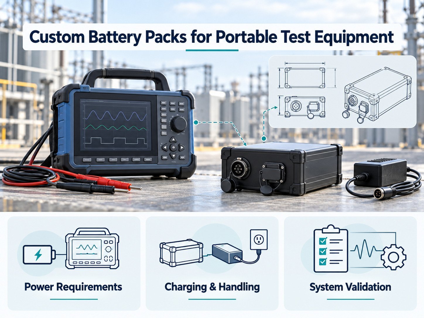
1. Define the Field Application
Start with how the instrument will be used.
Document:
- Type of measurement.
- Duration of each task.
- Number of tasks per working period.
- Indoor or outdoor use.
- Time between charging opportunities.
- Carrying and handling conditions.
- Required accessories.
- Data-saving and shutdown procedures.
Identify whether the instrument operates continuously or alternates between measurement and standby.
A battery requirement should reflect this schedule rather than an assumed constant load.
2. Build a Power Budget
List the circuits powered by the battery.
| Subsystem | Information to Record |
|---|---|
| Measurement circuits | Power during each measurement mode |
| Sensors and probes | Supply requirements and activation periods |
| Processing hardware | Startup, processing and idle consumption |
| ディスプレイ | Brightness settings and operating duration |
| コミュニケーション | Transmission, connection and standby activity |
| ストレージ | Recording and data-transfer demand |
| Auxiliary components | Fans, heaters, pumps or other fitted devices |
Include accessories that draw power from the instrument.
Identify which loads operate simultaneously. Record measured values separately from estimates.
3. Specify the Input-Voltage Range
The instrument needs a defined supply range.
Document:
- Permitted input voltage.
- Battery full-charge voltage.
- Normal discharge endpoint.
- Voltage behavior during load changes.
- Converter startup requirements.
- Undervoltage response.
- Shutdown and restart conditions.
Nominal battery voltage does not describe the entire operating range.
Review the battery together with the instrument’s power-conversion circuits. The measurement electronics may require regulated supply rails that are separate from the battery bus.
4. Calculate Energy From the Operating Schedule
For each operating stage:
Energy (Wh) = average battery-side power (W) × duration (h)
The following example illustrates the calculation.
| Operating Stage | Battery-Side Power | 期間 | エネルギー |
|---|---|---|---|
| Measurement | 18W | 2 hours | 36Wh |
| Data review | 10W | 1 hour | 10Wh |
| 待機中 | 2W | 2 hours | 4Wh |
| Total | — | — | 50Wh |
These figures are illustrative. They are not specifications for a particular instrument.
The calculated task energy does not automatically establish nominal battery capacity. Define the operating window, shutdown reserve, temperature conditions and service endpoint.
If measurements are taken at the battery output, avoid adding conversion losses already included in those readings.
5. Check Current Demand Separately
Energy requirements and current requirements serve different purposes.
A pack may contain the calculated task energy but still fail to support startup or a transient load.
Record:
- Continuous current.
- Transient current.
- Transient duration.
- Repetition rate.
- Battery voltage during the event.
- Temperature and state of charge.
Consider components such as pumps, illumination sources, printers and communication transmitters where fitted.
The current capability applies to the complete electrical path, including cells, protection components, wiring and connectors.
6. Evaluate Power-Supply Effects on Measurements
The battery, BMS, converters and charging arrangement form part of the instrument’s electrical system.
Switching activity, supply transients and grounding arrangements can interact with measurement circuits. Whether this affects results depends on the instrument design.
レビュー
- DC-DC converter operation.
- Supply ripple and transients.
- Grounding.
- Signal and power cable routing.
- Isolation requirements.
- BMS switching behavior.
- Operation while charging, if permitted.
Do not assume that battery operation eliminates electrical noise.
Validate measurement behavior in the instrument’s intended operating modes, using its defined accuracy requirements.
7. Decide Whether the Battery Is Removable
A removable pack can be part of the field-use arrangement, but it introduces mechanical and electrical interfaces that need definition.
Specify:
- Installation and removal procedure.
- Retention mechanism.
- Connector alignment.
- Contact protection.
- Handling features.
- Insertion-cycle requirements.
- Identification of compatible replacement packs.
If the pack is installed internally, define service access and who is authorized to replace it.
Do not describe a battery as user-replaceable unless the product has been designed and documented for that procedure.
8. Define Battery Replacement Behavior
If the instrument permits battery replacement during use, establish how power and data are handled.
Questions include:
- Must the instrument be switched off?
- Is there a separate hold-up power source?
- Can a measurement be interrupted?
- How is unsaved data handled?
- How does the instrument verify a replacement pack?
- What happens if the new connection is incomplete?
Hot-swapping requires a system design. It is not established by using a removable connector.
9. Coordinate BMS Functions With the Instrument
The BMS should support the approved battery construction and operating requirements.
主な職務内容は以下の通りです:
- Voltage and current monitoring.
- Temperature monitoring.
- Charge and discharge protection.
- State-of-charge reporting.
- Sleep and wake-up.
- Fault records.
- Communication.
Separate normal operating warnings from protective disconnection.
The instrument should have a defined response to battery warnings, including completing or interrupting a task and saving data.
Essential local battery protection should not depend solely on host communication.
10. Specify the Battery Information Shown to Users
Battery information should help users make defined operating decisions.
Possible displays include:
- State of charge.
- Charging status.
- Battery fault.
- Charging unavailable.
- Estimated runtime, where supported.
State of charge is an estimate. It does not directly establish the number of measurements remaining.
A runtime estimate requires a defined load model and validation under the intended operating modes.
Document how the display behaves when battery data is unavailable or invalid.
11. Define the Charging Method
Portable instruments may use a dedicated charger, an external adapter, a charging dock or a supported USB charging interface.
The selected arrangement must match the battery and equipment.
Specify:
- Input source.
- Charging voltage and current.
- Charging temperature limits.
- Termination behavior.
- Connector.
- Charge-control responsibility.
- Fault response.
For USB charging, document the supported power negotiation and fallback behavior. A USB connector shape alone does not establish the available charging power.
Operation During Charging
If measurements are allowed while charging, validate that mode separately.
Review power-path behavior, temperature, grounding and measurement performance.
Do not assume that an instrument can perform its specified measurements while connected to any external supply.
12. Account for Field Handling and Storage
Define the conditions encountered during carrying, use and storage.
These may include:
- Temperature.
- Dust.
- Moisture.
- Condensation.
- Cleaning.
- Vibration.
- Drops.
- Vehicle storage.
- Periods without use.
If an ingress protection rating is required, identify the tested assembly and connector condition.
A closed instrument case does not, by itself, establish protection for the installed battery.
Follow model-specific storage instructions. Do not apply one charge percentage or inspection interval to every pack.
13. Review Transport and Documentation Requirements
Identify the intended markets and how batteries will be shipped or carried.
Commercial shipments, batteries installed in equipment and spare batteries may involve different transport arrangements.
Where applicable, obtain transport test documentation matching the battery design and confirm packaging requirements.
Separately review the safety and conformity requirements for the complete instrument.
Battery documents do not automatically establish conformity of the measurement equipment.
14. Validate the Battery in the Instrument
Set acceptance criteria before testing.
| Test Area | Verification |
|---|---|
| Task energy | Completion of the defined operating schedule |
| 現在の需要 | Startup and transient behavior |
| Supply voltage | Operation across the approved range |
| Measurement performance | Results within the instrument’s stated requirements |
| 充電 | Profile, termination and fault handling |
| Battery reporting | Data interpretation and display behavior |
| Shutdown | Data preservation and power-down sequence |
| Mechanical integration | Retention, handling and replacement |
| Thermal operation | Cell and component temperatures |
| Storage recovery | Inspection, wake-up and return to use |
Record the battery model, hardware revision, firmware, instrument configuration and test conditions.
A bench discharge test does not establish every aspect of field operation.
15. What to Include in an OEM Battery RFQ
Provide the battery supplier with:
- Instrument description.
- Operating modes and schedule.
- Measured load profile.
- Input-voltage range.
- Required task energy.
- Current transients.
- Installation drawing.
- Mass allocation.
- Connector and communication requirements.
- Charging arrangement.
- Environmental conditions.
- Replacement and service procedures.
- Required documents.
- Validation responsibilities.
Mark unresolved requirements as open.
よくある質問
Can Battery Capacity Be Selected From Runtime Alone?
Not without power-consumption information and operating conditions. Current capability also needs separate assessment.
Does Battery Operation Prevent Measurement Noise?
No. The complete power and measurement architecture requires validation.
Can the Instrument Be Used While Charging?
Only if that mode is part of the approved design and has been verified.
Can Users Replace the Battery?
That depends on the mechanical design, electrical interfaces and documented procedure.
Can One Pack Be Used Across Several Instruments?
Possibly, if compatibility is defined and validated for each instrument configuration.
Preparing the Battery Specification
Begin with the instrument’s measurement task and operating schedule.
Define energy, current, supply behavior, charging and handling requirements. Validate the battery within the intended instrument before approving the production configuration.




 English
 Chinese
 Japanese
 German
 French
 Korean

