
When a lithium battery pack is connected to an electrical device, a visible spark may sometimes appear at the connector. This phenomenon is commonly caused by high inrush current flowing into the input capacitors of the connected equipment.
For low-power devices, a small spark may appear harmless. However, repeated arcing can damage connector contacts, increase electrical wear, generate electromagnetic interference, and create reliability concerns in high-current battery applications.
A properly designed battery pack anti-spark protection system can reduce this problem by controlling the initial current flow between the battery and the load.
For battery pack manufacturers and OEM customers, anti-spark protection can be integrated into the battery architecture through pre-charge circuits, MOSFETs, relays, contactors, anti-spark connectors, and BMS control logic.
This article explains how battery pack anti-spark protection works, how to design a pre-charge circuit, and what OEM/ODM customers should consider when specifying a custom lithium battery pack.
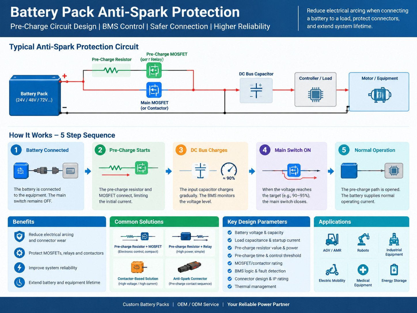
What Is Battery Pack Anti-Spark Protection?
Battery pack anti-spark protection is a circuit or connection method designed to reduce electrical arcing when a battery is connected to a load.
The basic problem occurs when the load contains a large input capacitor.
A typical system may look like:
Lithium Battery → Connector → Controller → DC Bus Capacitor
Before the battery is connected, the DC bus capacitor may be nearly discharged.
When the connector is inserted, the battery attempts to charge this capacitor immediately. Because the initial capacitor voltage is close to zero, the resulting current can be very high.
The current can be approximated by:
I = V / R
where:
- I = initial current
- V = battery voltage
- R = total circuit resistance
The total resistance includes the battery internal resistance, cable resistance, connector resistance, MOSFET resistance, and other circuit resistance.
If this current is high enough, an electrical arc can form between connector contacts.
An anti-spark circuit introduces controlled resistance or a controlled switching sequence to limit this initial current.
Why Does a Battery Pack Produce a Spark?
The most common reason is capacitive inrush current.
Consider a 48 V battery connected to a motor controller with a large DC-link capacitor.
Before connection:
Battery = 48 V
DC Bus Capacitor ≈ 0 V
After connection, the capacitor tries to rapidly charge toward 48 V.
The charging current can initially be very high.
Without current limiting:
48 V Battery
     │
     │
 Connector
     │
     ▼
Large Capacitor
     │
     ▼
High Inrush Current
     │
     ▼
Electrical Arc
With a pre-charge circuit:
48 V Battery
     │
     ├── Pre-Charge Resistor ──┐
     │                         │
     │                    DC Bus Capacitor
     │                         │
     └── Main Switch ──────────┘
The pre-charge resistor limits the initial current.
After the capacitor voltage reaches the required level, the main switching path can close.
How Does a Battery Pack Pre-Charge Circuit Work?
A typical anti-spark battery pack uses a controlled sequence.
Step 1: Battery Connection
The battery is connected to the equipment.
The main high-current path remains disconnected.
Step 2: Pre-Charge Starts
A pre-charge MOSFET or relay connects the battery to the load through a resistor.
The resistor limits the charging current.
Step 3: DC Bus Voltage Increases
The equipment’s input capacitor gradually charges.
The voltage difference between the battery and DC bus decreases.
Step 4: Pre-Charge Completion
The BMS or control circuit monitors the voltage.
When the DC bus voltage reaches a predefined percentage of battery voltage, the system determines that pre-charge is complete.
Step 5: Main Power Path Closes
The main MOSFET, relay, or contactor turns on.
The pre-charge resistor is bypassed.
The battery can then supply the normal operating current.
This sequence significantly reduces the current surge during connection.
Common Battery Anti-Spark Protection Solutions
Different applications require different approaches.
1. Pre-Charge Resistor + MOSFET
A MOSFET-controlled pre-charge branch can provide electronic control over the initial current.
Typical structure:
Battery +
   │
   ├──── Pre-Charge Resistor ── MOSFET ───┐
   │                                      │
   └──────── Main MOSFET ─────────────────┤
                                          │
                                       Load +
Les avantages sont les suivants
- Electronic control
- Fast switching
- Conception compacte
- Easy integration with BMS
- Suitable for custom battery packs
This solution is useful for robots, AGVs, industrial equipment, and other battery-powered systems.
2. Pre-Charge Resistor + Relay
A relay can be used to control the pre-charge sequence.
The basic operating logic is:
Pre-charge relay ON → capacitor charging → main relay ON → pre-charge relay OFF
This architecture is commonly used in higher-power systems where mechanical switching components are appropriate.
The relay and resistor must be selected according to:
- Maximum battery voltage
- Courant continu
- Courant de crête
- Capacitor size
- Switching frequency
- Conditions environnementales
3. Contactor-Based Pre-Charge System
For high-voltage or high-current battery systems, contactors can be used with a dedicated pre-charge circuit.
The sequence may be:
Negative contactor ON → pre-charge contactor ON → DC bus charging → positive contactor ON → pre-charge contactor OFF
This architecture is commonly considered for industrial vehicles, energy systems, mobile machinery, and high-power equipment.
4. Anti-Spark Connector
Some battery applications use connectors specifically designed to reduce arcing.
An anti-spark connector may include a dedicated pre-charge contact.
The connection sequence can be designed so that:
Pre-charge contact → Main power contact
During disconnection, the sequence can operate in reverse.
This approach can be useful for removable battery systems where users frequently connect and disconnect the battery.
How to Calculate a Pre-Charge Resistor
Pre-charge resistor selection should be based on the battery voltage, target current, load capacitance, and desired charging time.
A basic starting calculation is:
R = V / I
For example, assume:
- Battery voltage = 48 V
- Target pre-charge current = 2 A
The theoretical resistance is:
R = 48 / 2 = 24 Ω
A resistor around this value may be considered as a starting point.
However, resistor selection should not stop at Ohm’s law.
The resistor must also withstand the energy generated during capacitor charging.
The energy stored in a capacitor is:
E = 1/2 × C × V²
where:
- E = stored energy
- C = capacitance
- V = charging voltage
For example, if the DC bus capacitance is 2,000 μF and the voltage is 48 V:
E = 1/2 × 0.002 × 48²
E ≈ 2.30 J
The actual resistor specification should account for pulse energy, repetition rate, thermal conditions, tolerance, and the complete circuit behavior.
For production battery packs, engineering validation should be performed rather than selecting the resistor based only on a theoretical calculation.
How Long Should Pre-Charging Take?
Pre-charge time depends mainly on the RC characteristics of the system.
For a simplified RC circuit:
τ = R × C
where:
- τ = time constant
- R = pre-charge resistance
- C = load capacitance
The capacitor voltage follows an exponential charging curve.
Approximately:
- 1τ → 63.2%
- 2τ → 86.5%
- 3τ → 95.0%
- 4τ → 98.2%
- 5τ → 99.3%
This means engineers can estimate the pre-charge time based on the required final voltage.
For example, if the system requires the DC bus to reach approximately 90% of battery voltage before closing the main switch, the control logic can be designed around the calculated RC time.
Actual design should also account for load leakage, DC/DC converters, controller behavior, temperature, component tolerances, and voltage measurement accuracy.
BMS Control for Anti-Spark Protection
The BMS can play an important role in controlling the anti-spark process.
A smart BMS may monitor:
- Tension de la batterie
- Potentiel cellulaire
- Pack current
- MOSFET temperature
- Pre-charge voltage
- Load voltage
- Short-circuit conditions
- Over-current conditions
- Connection status
A simplified control sequence is:
Battery Connected
       ↓
System Check
       ↓
Pre-Charge ON
       ↓
Monitor DC Bus Voltage
       ↓
Voltage Reaches Target
       ↓
Main Power ON
       ↓
Pre-Charge OFF
       ↓
Normal Operation
If the DC bus voltage does not rise as expected, the BMS can stop the pre-charge process.
This can help identify conditions such as:
- Court-circuit
- Incorrect load
- Excessive capacitance
- Pre-charge resistor failure
- MOSFET failure
- Wiring problems
MOSFET-Based Anti-Spark Protection
MOSFETs are frequently used in battery packs because they provide electronic switching without mechanical contact wear.
For a MOSFET-based design, engineers should evaluate:
Voltage Rating
The MOSFET voltage rating should provide an appropriate margin above the maximum battery voltage and transient voltage.
Current Rating
The MOSFET must handle both continuous current and transient conditions.
RDS(on)
Lower RDS(on) reduces conduction losses.
The conduction loss can be estimated as:
P = I² × RDS(on)
At high current, even a small resistance can generate significant heat.
Thermal Management
MOSFET temperature depends on:
- Actuel
- RDS(on)
- Switching frequency
- PCB copper area
- Enclosure design
- Température ambiante
- Thermal interface
Therefore, electrical and thermal design should be evaluated together.
Anti-Spark Protection for High-Current Lithium Battery Packs
High-current applications require additional attention because the potential energy is substantial.
Parmi les applications courantes, on peut citer :
- Batteries AGV
- AMR batteries
- Robot batteries
- Forklift batteries
- Golf cart batteries
- Industrial equipment batteries
- Electric mobility systems
- Floor cleaning machines
- Équipement maritime
- Systèmes de stockage d'énergie
For these applications, an anti-spark system may need to work together with:
BMS + MOSFET/Contactor + Pre-Charge Circuit + Fuse + Current Sensor + Temperature Monitoring
The battery pack should be designed as an integrated electrical system rather than treating anti-spark protection as an isolated component.
Battery Connector Design and Anti-Spark Protection
The connector itself can influence arcing.
Parmi les paramètres importants, on peut citer :
- Rated voltage
- Rated current
- Contact resistance
- Contact sequence
- Insertion force
- Number of mating cycles
- Matériau du boîtier
- Insulation characteristics
- Environmental protection
- Indice de protection IP
For frequently removable batteries, the connector should be evaluated together with the anti-spark strategy.
A connector rated for a particular continuous current does not necessarily mean it can safely handle repeated high-current capacitor charging during connection.
This distinction is important when designing battery systems for industrial equipment.
Battery Pack Anti-Spark Protection vs. Basic BMS Protection
Anti-spark protection and standard BMS protection are related but serve different purposes.
| Function | Main Purpose |
|---|---|
| Protection contre les surcharges | Prevent excessive cell charging |
| Protection contre la surcharge | Prevent excessive cell discharge |
| Protection contre les surintensités | Limit excessive operating current |
| Protection contre les courts-circuits | Disconnect abnormal current |
| Protection de la température | Control unsafe thermal conditions |
| Pre-charge protection | Control capacitor charging current |
| Anti-spark protection | Reduce arcing during connection |
A battery can have a BMS and still require a dedicated pre-charge strategy.
This is because a conventional BMS protection circuit may disconnect the battery after an abnormal current is detected, but it does not necessarily eliminate the initial transient that causes connector arcing.
How to Specify an Anti-Spark Battery Pack for OEM Projects
When requesting a custom battery pack, the OEM customer should provide as much system information as possible.
Important specifications include:
Battery Parameters
- Tension nominale
- Maximum charging voltage
- Capacité
- Courant de décharge continu
- Courant de décharge maximal
- Chimie des batteries
Load Parameters
- Equipment operating voltage
- Rated power
- Peak power
- Motor type
- Controller type
- DC bus capacitance
- Courant de démarrage
Environmental Parameters
- Température de fonctionnement
- Température de charge
- Humidité
- Vibrations
- Waterproofing requirements
- Installation environment
Control Requirements
- Pre-charge time
- Main switching method
- BMS communication
- Communication CAN
- Détection des défauts
- Remote wake-up
- Sleep mode
These parameters allow the battery manufacturer to design the anti-spark system according to the actual equipment rather than using a generic circuit.
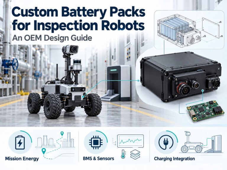
Anti-Spark Protection for AGV and AMR Batteries
AGVs and AMRs are a particularly relevant application because their battery systems may experience frequent charging, battery replacement, and high-current motor operation.
A custom AGV battery can integrate:
- Cellules LiFePO4
- Smart BMS
- Communication CAN
- Pre-charge circuit
- Main contactor
- Current sensor
- Capteurs de température
- Fuse
- Surveillance du SOC
- Fault diagnosis
The pre-charge function can be coordinated with the vehicle controller.
Par exemple :
Battery Installed → System Wake-Up → Pre-Charge → DC Bus Ready → Main Power ON → AGV Operation
This architecture can help reduce connector arcing and provide controlled system startup.
Anti-Spark Protection for Robot Battery Packs
Robotic systems can also have substantial input capacitance because motor controllers, servo drives, and DC/DC converters often contain capacitors.
Robot battery packs may therefore require:
- Compact BMS
- High-current MOSFETs
- Pre-charge circuit
- Contrôle de la température
- Interface de communication
- Mechanical protection
- Custom connectors
For mobile robots, the battery pack size and weight can also affect the selection of switching components and thermal design.
Testing a Battery Pack Anti-Spark System
A custom battery pack should undergo functional and reliability testing.
Recommended testing may include:
Pre-Charge Functional Test
Verify that the DC bus reaches the target voltage within the specified time.
Repeated Connection Test
Test repeated battery connection and disconnection cycles.
High-Current Test
Verify that the main switching path can support the required continuous and peak current.
Temperature Test
Monitor:
- MOSFET temperature
- Resistor temperature
- Connector temperature
- BMS temperature
Short-Circuit Protection Test
Verify that abnormal conditions trigger the appropriate protection response.
Load Compatibility Test
Test the actual battery with the target controller or equipment.
For OEM projects, testing with the real load is particularly important because different controllers can have very different input capacitance and startup characteristics.
Common Problems in Battery Anti-Spark Design
Problem 1: Pre-Charge Time Is Too Long
Possible causes include:
- Resistance too high
- Load capacitance too large
- Load consumes power during pre-charge
- Incorrect control threshold
Problem 2: Spark Still Appears
Possible causes include:
- Pre-charge circuit is bypassed
- Pre-charge resistance is too low
- Main contact closes too early
- Connector design does not support the intended sequence
- Load contains additional capacitive circuits
Problem 3: Pre-Charge Resistor Overheats
Possible causes include:
- Repeated pre-charge cycles
- Excessive capacitor energy
- Insufficient resistor pulse rating
- Incorrect resistance
- Insufficient cooling
Problem 4: MOSFET Overheats
Possible causes include:
- Courant excessif
- High RDS(on)
- Insufficient thermal dissipation
- Incorrect MOSFET selection
- Switching losses
These problems demonstrate why anti-spark protection should be designed together with the complete battery and load system.
Why OEM Battery Pack Design Matters
There is no universal anti-spark circuit that fits every lithium battery application.
A 24 V robot battery, 48 V AGV battery, 72 V industrial battery, and high-voltage energy system may require different switching architectures.
A custom battery manufacturer can evaluate:
Battery → BMS → Pre-Charge → Switching → Connector → Controller → Load
as one complete system.
This approach allows the battery pack design to address electrical, mechanical, thermal, communication, and safety requirements simultaneously.
Custom Battery Pack Anti-Spark Solutions
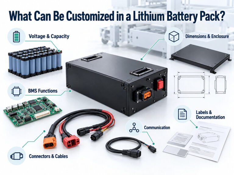
For OEM and ODM battery projects, anti-spark protection can be integrated into a customized battery architecture based on the equipment requirements.
A battery manufacturer may provide:
- Custom battery voltage
- Custom capacity
- Li-ion or LiFePO4 chemistry
- BMS sur mesure
- Pre-charge circuit
- MOSFET protection
- Relay or contactor control
- Communication CAN
- Custom connector
- Boîtier conforme à la norme IP
- Gestion thermique
- Tests fonctionnels
- Développement de prototypes
- Soutien à la certification
For applications such as AGVs, AMRs, robots, industrial equipment, electric mobility, medical equipment, and mobile machinery, the anti-spark function can be designed as part of the complete battery pack rather than added after production.
FAQ
What causes sparks when connecting a lithium battery?
The most common cause is high inrush current from charging the input capacitors of the connected equipment.
Does every lithium battery need anti-spark protection?
Not necessarily. The requirement depends on the battery voltage, load characteristics, connector design, capacitance, current level, and connection method.
Does a BMS prevent battery sparks?
A standard BMS provides protection functions such as over-current and short-circuit protection, but it does not automatically provide a complete pre-charge or anti-spark function.
What is a pre-charge resistor?
A pre-charge resistor temporarily limits current while the load-side capacitor charges.
Can MOSFETs be used for anti-spark protection?
Yes. MOSFETs can provide electronically controlled pre-charge and main power switching in many battery pack designs.
How do I choose a pre-charge resistor?
The basic starting point is the target pre-charge current and battery voltage. Final selection also requires consideration of load capacitance, charging time, pulse energy, repetition rate, and thermal conditions.
Can anti-spark protection be integrated into a custom battery pack?
Yes. A battery manufacturer can integrate the pre-charge circuit, MOSFETs, relays or contactors, BMS, current sensing, and connectors according to the target equipment.
Conclusion
Battery pack anti-spark protection is primarily about controlling inrush current during connection.
For systems with significant input capacitance, a properly designed pre-charge circuit can reduce electrical arcing and help protect connectors and switching components.
A complete solution may combine:
Pre-Charge Resistor + MOSFET/Relay/Contactor + BMS + Current Monitoring + Voltage Monitoring + Proper Connector Design
For OEM/ODM battery projects, the correct solution depends on the actual battery voltage, load capacitance, current requirements, operating environment, and control architecture.
By designing the battery pack and anti-spark system together, manufacturers can create a battery solution that is compatible with the target equipment and its operating requirements.
 English
  Chinese
  Japanese
  German
  French
  Korean
