
A lithium battery pack can be designed around the electrical, mechanical and operating requirements of a device.
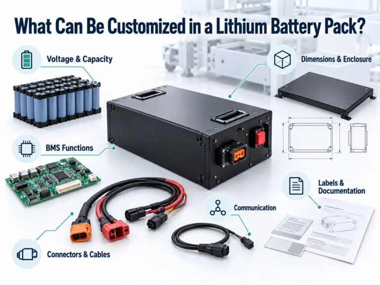
Customization may involve voltage, capacity, dimensions, connectors, BMS functions, communication and documentation. These choices are connected. Changing one requirement can affect other parts of the design.
This guide explains the items OEMs can specify, the information suppliers need and the checks required before production.
Battery Pack Customization at a Glance
| Objet | What Can Be Specified | Information Needed |
|---|---|---|
| Tension | Cell chemistry and series configuration | Equipment input-voltage range |
| Capacité | Cell model and parallel configuration | Energy demand and operating duration |
| Actuel | Discharge capability and protection settings | Continuous and transient loads |
| Dimensions | Cell arrangement and pack shape | Installation drawing and clearances |
| Enclosure | Material, mounting and access features | Environment and handling requirements |
| Interfaces | Connectors, cables and pin assignments | Equipment connection details |
| BMS | Monitoring, protection and operating behavior | Functional requirements |
| Communication | Data interface and application messages | Host protocol |
| Charging | Charger interface and control requirements | Charging schedule and system design |
| Documentation | Labels, records and instructions | OEM identification and delivery requirements |
Each item requires engineering review. A customization request does not establish feasibility until the design has been assessed.
1. Voltage and Battery Configuration
Battery voltage is determined by cell chemistry and the number of cells or groups connected in series.
The OEM should provide the equipment’s permitted input range, including charging and discharge conditions.
Specify:
- Nominal voltage.
- Full-charge voltage.
- Normal discharge endpoint.
- Voltage limits of connected electronics.
- Startup requirements.
- Regenerative charging conditions, if applicable.
A nominal voltage label does not define the complete operating range.
The charger, controller and other electronics must be compatible with the selected configuration.
2. Capacity and Energy
Capacity can be specified through cell selection and pack configuration, subject to space, mass and operating constraints.
Provide the required task duration and load profile.
For preliminary planning:
Nominal energy (Wh) = nominal voltage (V) × capacity (Ah)
A nominal 24V, 10Ah pack has a calculated nominal energy of 240Wh. This does not establish usable energy under every condition.
The specification should distinguish:
- Nominal capacity.
- Minimum capacity.
- Capacity measurement conditions.
- Required usable energy.
- Performance at the defined service endpoint.
Avoid selecting capacity from runtime alone without documenting power consumption.
3. Continuous and Transient Current
The electrical path can be designed for a defined load profile.
That path includes cells, interconnections, protective devices, BMS components, cables and connectors.
Provide:
- Continuous current.
- Transient current.
- Transient duration.
- Repetition rate.
- Operating temperature.
- Permitted voltage drop.
A request such as “suitable for a motor” needs the controller specifications and operating conditions.
The current rating of one component does not establish the rating of the complete pack.
4. Dimensions and Cell Arrangement
The pack shape can be developed around an equipment installation space.
Depending on the design, this may involve cylindrical, prismatic or pouch cells arranged within a defined envelope.
Provide a drawing or model showing:
- Available space.
- Dimensional tolerances.
- Mounting points.
- Connector locations.
- Cable routes.
- Removal path.
- Service access.
- Mass limits.
The full installation envelope includes the enclosure, insulation, wiring and required clearances.
A pack that fits a rectangular space on paper still needs an installation check in the equipment.
5. Enclosure and Mounting Features
Enclosure customization may include:
- Material.
- Shape.
- Mounting brackets.
- Handles.
- Locks and latches.
- Covers.
- Cable exits.
- Connector openings.
- Surface finish.
- Product identification.
Selection should follow handling, installation and environmental requirements.
For removable packs, define how the user inserts, secures, carries and removes the battery.
If ingress protection is required, specify the assembled configuration and test conditions. Enclosure material or seal selection alone does not establish an IP rating.
6. Connectors and Cable Assemblies
Interfaces can be specified to match the equipment’s approved connection.
Document:
- Connector manufacturer and part number.
- Mating connector.
- Pin assignment.
- Polarity.
- Cable type and length.
- Length tolerance.
- Exit direction.
- Strain relief.
- Signal functions.
For repeated battery removal, include insertion cycles, alignment and retention in the verification plan.
Matching connector shapes do not establish electrical compatibility.
7. BMS Functions and Settings
The battery management system can be selected or developed for the functions required by the application.
Depending on the hardware and software, these may include:
- Voltage monitoring.
- Current measurement.
- Temperature sensing.
- Charge and discharge protection.
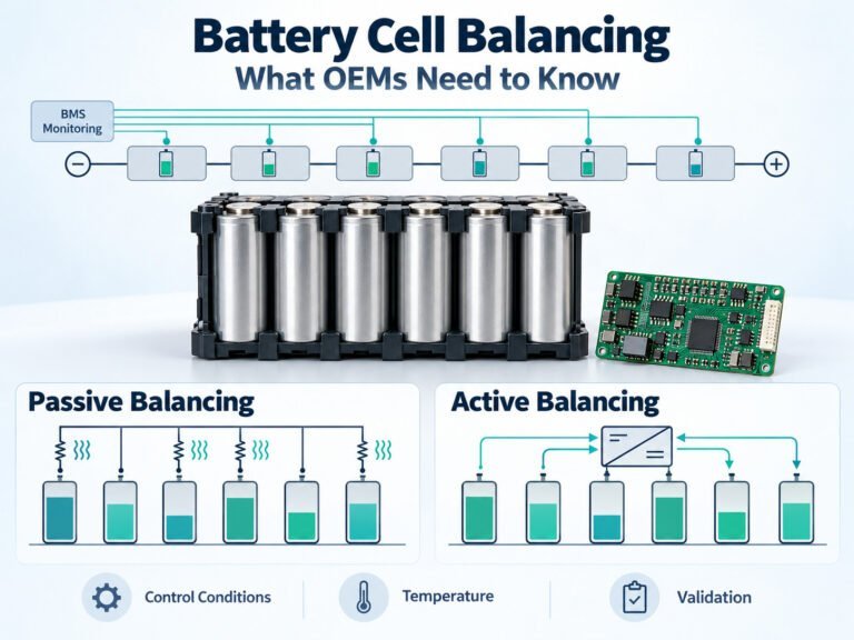
- Cell balancing.
- Fault records.
- State-of-charge reporting.
- Sleep and wake-up.
- Host commands.
Not every BMS supports every function.
Protection settings must remain within the approved cell, component and system limits. They should not be changed simply to accommodate an unverified load.
Record the hardware revision, firmware and configuration used in the approved design.
8. Communication With Equipment
A battery can include a communication interface where the application requires it.
Examples include CAN, RS485, SMBus and UART-based connections.
The OEM should provide the host protocol, not only the interface name.
Define:
- Communication settings.
- Messages or register addresses.
- Units and scaling.
- Byte order.
- Update intervals.
- Timeouts.
- Fault meanings.
- Command permissions.
- Version handling.
The battery and host need system-level testing. Interface support alone does not establish compatibility.
9. Charging Arrangement
Charging customization may involve the connector, charge-control interface, charger selection and operating sequence.
Specify:
- Charging voltage and current.
- Temperature limits.
- Termination behavior.
- Available charging time.
- Manual or automatic connection.
- Communication requirements.
- Operation during charging, if required.
The charging arrangement must match the cells, BMS and equipment.
A requested charging time requires verification under defined conditions. It should not be presented as a guaranteed result before testing.
10. Temperature Monitoring and Thermal Integration
Sensor quantity and placement can be specified within the battery design.
The arrangement should reflect:
- Cell layout.
- Heat-generating components.
- Installation airflow.
- Enclosure conditions.
- Equipment heat sources.
- Required fault detection.
Record what each sensor measures and how the BMS responds.
Ambient temperature does not establish the temperature at every cell or component. Validate the battery in its intended installation.
11. Labels and OEM Documentation
Customization can include product identification and delivery documents.
En voici quelques exemples :
- OEM model number.
- Serial-number format.
- Parameter label.
- Barcode or QR code.
- Interface drawing.
- User instructions.
- Inspection records.
- Packaging labels.
Parameter values must match the approved product.
Certification logos may only be used under the applicable authorization. Adding a logo to a label does not establish certification.
Agree on document languages, revision control and the records supplied with each shipment.
12. Packaging
Packaging can be developed for the product dimensions, handling process and transport arrangement.
Define:
- Battery quantity per package.
- Internal restraint.
- Terminal protection.
- Accessory placement.
- Required marks and labels.
- Handling instructions.
Transport requirements need their own review. Damaged or defective batteries must not be treated as ordinary undamaged shipments.
Confirm packaging responsibilities when requesting a quotation.
What Limits Battery Customization?
Customization is subject to physical, electrical, manufacturing and compliance constraints.
En voici quelques exemples :
- Available cell models.
- Cell operating limits.
- Installation space.
- Mass allocation.
- Component ratings.
- Heat dissipation.
- Manufacturing processes.
- Test requirements.
- Order quantities.
- Project schedule.
Requirements may conflict. A fixed enclosure, specified energy and defined current profile must be reviewed together.
The supplier should identify unresolved requirements and design assumptions before approval.
How to Start a Custom Battery Project
Step 1: Describe the Equipment
Explain what the device does, where it operates and how it is charged.
Step 2: Provide Drawings and Measurements
Supply the installation envelope, electrical load profile and host-interface information.
Step 3: Separate Requirements From Preferences
Identify mandatory limits, preferred features and items still open for discussion.
Step 4: Agree on the Proposed Design
Review the cells, configuration, BMS, interfaces, enclosure and charging arrangement.
Step 5: Define Validation
Set test conditions, acceptance criteria and responsibilities before sample testing.
Step 6: Approve the Production Configuration
Record the approved construction, settings, documents and change-control process.
OEM Customization Checklist
| Category | Information to Prepare |
|---|---|
| Application | Device function and operating environment |
| Electrical | Voltage range and load profile |
| L'énergie | Task duration and usable-energy requirement |
| Mechanical | Drawings, mounting and mass limits |
| Interfaces | Connectors, wiring and communication |
| Charging | Charger and operating schedule |
| Environnement | Temperature, moisture, vibration and storage |
| Service | Removal, maintenance and replacement |
| Compliance | Markets and required documents |
| Production | Quantities, traceability and change control |
Foire aux questions
Can a Battery Be Made to Fit an Existing Device?
Possibly. The available space must support the required cells, structure, electrical connections and operating conditions.
Can Capacity Change Without Changing the Enclosure?
That depends on the cell options and existing design. Review current capability, thermal behavior and document coverage.
Can an Existing Charger Be Retained?
Only if its characteristics and control behavior match the approved battery design.
Can BMS Settings Be Customized?
Where supported, settings can be configured within the approved design limits.
Can One Battery Work With Several Equipment Models?
Yes, if compatibility is defined and validated for each intended configuration.
Defining the Custom Battery Scope
Start with the equipment requirements rather than an isolated battery parameter.
Document the electrical, mechanical, charging and communication interfaces. Confirm feasibility, validate the proposed design and approve the production configuration before supply.

 English
 Chinese
 Japanese
 German
 French
 Korean

