
A medical battery pack is not simply a group of lithium-ion cells connected to a power output. It is part of the medical equipment’s electrical system, supporting functions such as portable operation, battery backup, charging, and power management.
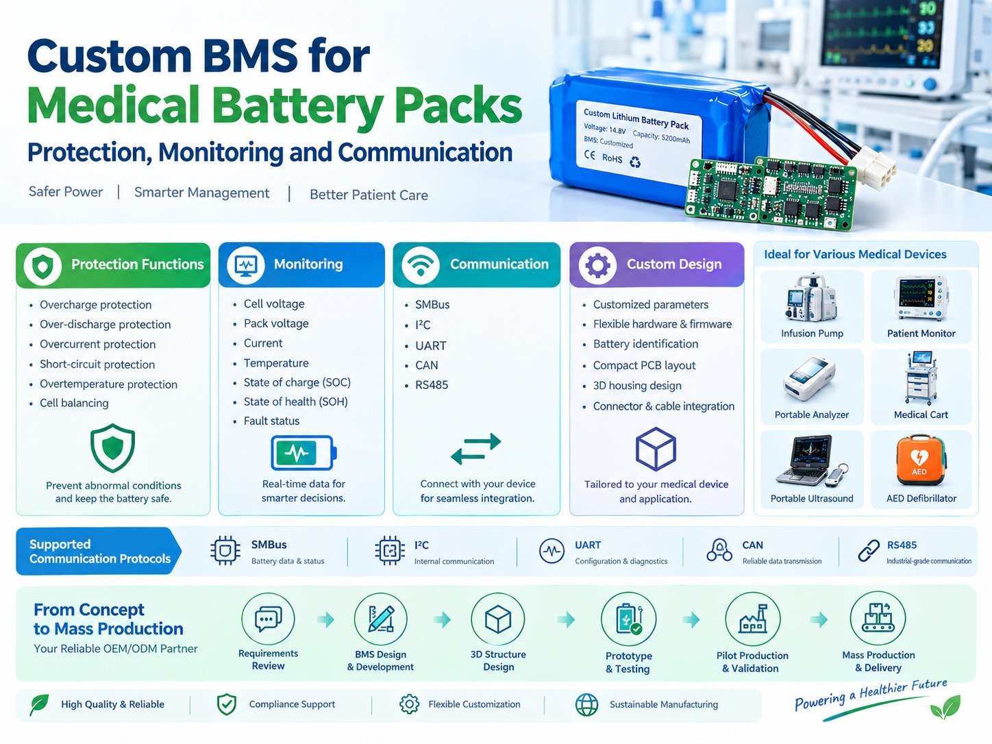
The Battery Management System, commonly known as BMS, plays an important role in managing rechargeable lithium battery packs. It monitors battery conditions, implements protection functions, and may communicate with the medical device to provide battery information.
For OEM and ODM medical equipment projects, a standard BMS board may not provide the required protection parameters, communication interface, battery identification, or mechanical compatibility. A custom BMS can be developed according to the battery configuration and the equipment’s operating requirements.
This technical guide explains how a custom BMS works in medical battery packs, what functions should be considered during development, and how medical equipment manufacturers can work with a battery supplier to create an integrated battery solution.
1. What Is a Custom BMS for Medical Battery Packs?
A custom BMS is a battery management system designed or configured for a specific battery pack and its application.
It may include customized hardware, firmware, protection parameters, communication functions, and battery monitoring algorithms.
For medical equipment, the BMS should be designed around the complete battery system, including:
- Cell chemistry
- Zellkonfiguration
- Nennspannung
- Ladespannung
- Entladungsstrom
- Spitzenlast
- Betriebstemperatur
- Akkukapazität
- Equipment communication
- Battery housing
- Charging architecture
A BMS designed for a 4S lithium-ion battery pack cannot automatically be used in a 3S or 8S battery pack without reviewing the circuit, voltage measurement range, protection parameters, balancing design, and firmware.
The same principle applies to medical equipment. A BMS developed for a portable blood analyzer may require different functions from one used in a medical cart or emergency medical device.
Standard BMS vs. Custom BMS
| Design Factor | Standard BMS | Benutzerdefiniertes BMS |
|---|---|---|
| Zellkonfiguration | Fixed or limited configurations | Designed for the specified battery |
| Protection parameters | Predefined | Configured according to cell and application requirements |
| Kommunikation | Available interfaces may be fixed | Interface and data requirements can be adapted |
| Battery identification | May be unavailable | Can support model and battery identification |
| Housing | Standard PCB dimensions | PCB and enclosure designed around the battery |
| Firmware | Existing functions | Custom functions and parameter management |
| Equipment integration | Requires compatibility verification | Developed with the equipment requirements in mind |
| Development process | Shorter for compatible applications | Includes engineering and validation stages |
A custom BMS does not mean that every component must be developed from scratch. Some projects can use an established BMS platform with customized hardware, firmware, and parameters. Other projects may require a new circuit or communication design.
The appropriate development approach depends on the medical equipment’s requirements.
2. Why Medical Equipment May Need a Custom BMS
Medical devices can have specific power requirements that are not addressed by a general-purpose battery protection board.
For example, a portable medical analyzer may need stable power during a measurement cycle, while a patient monitor may need to report battery status continuously during operation.
A medical cart may require a replaceable battery, charging management, and communication with the equipment’s main control system.
A custom BMS can help address these requirements through coordinated electrical and software design.
2.1 Application-Specific Protection
The BMS protection thresholds should match the selected cell chemistry and battery configuration.
Zu den wichtigen Parametern gehören:
- Overcharge protection voltage
- Over-discharge protection voltage
- Overcurrent threshold
- Short-circuit protection response
- Overtemperature threshold
- Charging temperature range
- Discharging temperature range
- Cell balancing conditions
These parameters should be verified against the cell manufacturer’s specifications and the equipment’s operating requirements.
For example, the allowable charging voltage of a lithium-ion NMC battery pack differs from that of a LiFePO4 battery pack. A BMS configuration should not be transferred between chemistries without appropriate engineering review.
2.2 Battery Status Monitoring
A medical device may need information about remaining battery capacity, charging status, temperature, or battery faults.
A custom BMS can be designed to measure and report relevant battery data.
Depending on the design, the BMS may monitor:
- Spannung einer einzelnen Zelle
- Total pack voltage
- Pack current
- Cell temperature
- PCB temperature
- Ladezustand
- State of health
- Ladezustand
- Discharge status
- Fault conditions
The equipment manufacturer should define which information is needed by the main control system and how the information will be used.
2.3 Mechanical and Electrical Integration
Medical equipment often has a limited installation space.
The BMS may need to fit inside a compact battery housing, connect to a specific connector, or communicate through an existing wiring harness.
A custom BMS design can consider:
- PCB dimensions
- Anschlussposition
- Mounting holes
- Kabelverlegung
- Insulation
- Battery housing
- Thermal conditions
- Service access
This is particularly important when the battery pack is designed for an existing medical device.
3. Core Protection Functions in a Custom Medical BMS
Protection functions help prevent battery operation outside specified electrical and thermal limits.
The BMS should be designed to respond to defined abnormal conditions. It is not a substitute for the complete medical device safety system.
3.1 Overcharge Protection
Overcharge protection monitors cell voltage during charging.
If a cell reaches the configured protection threshold, the BMS may interrupt charging through the appropriate control circuit.
The protection threshold depends on:
- Cell chemistry
- Cell manufacturer’s specification
- Series configuration
- Ladeverfahren
- BMS measurement accuracy
- Equipment charging requirements
The BMS should also account for cell voltage differences. In a series-connected battery pack, one cell may reach its voltage limit before the others.
3.2 Over-Discharge Protection
Over-discharge protection monitors cell voltage during discharge.
When a cell reaches the configured lower voltage threshold, the BMS may disconnect the discharge path to protect the battery.
For medical equipment, this function should be considered alongside the device’s low-battery warning and shutdown strategy.
For example, a portable diagnostic device may need to provide a warning before the battery reaches a condition where the BMS disconnects the load.
The warning threshold and BMS cutoff threshold should be coordinated during equipment-level testing.
3.3 Overcurrent Protection
Overcurrent protection monitors the current flowing through the battery pack.
The BMS may detect:
- Excessive continuous current
- Short-duration current overload
- Abnormal charging current
- Short-circuit conditions
The protection settings should account for the equipment’s normal startup current and peak operating demand.
A medical device with a motor, pump, compressor, or other transient load may require a different protection strategy from a device with a relatively constant power demand.
3.4 Short-Circuit Protection
Short-circuit protection is designed to respond to a rapid and abnormal current increase.
The response depends on the BMS circuit, current measurement method, protection threshold, and system architecture.
The design should consider:
- Short-circuit detection
- Protection response time
- MOSFET or switching device characteristics
- Wiring resistance
- Connector behavior
- Fault recovery
- Equipment restart conditions
Short-circuit protection should be tested using a defined procedure and appropriate laboratory equipment.
3.5 Temperature Protection
Temperature monitoring is important because lithium battery performance and safety depend on operating temperature.
A custom BMS may use temperature sensors to monitor:
- Cell temperature
- Battery pack temperature
- BMS PCB temperature
- Ladetemperatur
- Entladetemperatur
The BMS may prevent charging or discharging when the measured temperature exceeds the configured operating range.
The temperature sensor location is important. A sensor placed far from the cells may not accurately represent the temperature of the battery’s hottest area.
For medical battery packs, thermal testing should consider the actual housing, charging method, load profile, and operating environment.
4. Cell Balancing in Medical Battery Packs
Cell balancing helps manage voltage differences between cells connected in series.
During charging and discharging, cells may develop differences in voltage because of variations in capacity, internal resistance, temperature, and aging.
A BMS may use passive or active balancing.
Passive Balancing
Passive balancing typically reduces the voltage of selected cells by dissipating a small amount of energy through a resistor.
Die Vorteile sind:
- Relatively simple circuit design
- Lower hardware complexity
- Established implementation methods
The balancing current and activation conditions depend on the BMS design.
Active Balancing
Active balancing transfers energy between cells or cell groups.
This approach may be considered for certain battery configurations where balancing efficiency and energy transfer are important.
The selection depends on:
- Batteriegröße
- Zellkonfiguration
- Balancing current
- Kosten
- Thermal requirements
- Battery operating profile
For many medical battery pack applications, passive balancing may be suitable, but the final design should be based on the battery’s requirements.
Why Balancing Matters
Cell voltage consistency can affect:
- Usable battery capacity
- Charging behavior
- Protection events
- Batteriealterung
- Pack performance
For a series-connected battery, the BMS should monitor individual cell voltages rather than relying only on total pack voltage.
A custom BMS can be configured to support the required cell monitoring channels and balancing strategy.
5. Custom BMS Communication with Medical Equipment
Communication is one of the main reasons an OEM/ODM project may require a custom BMS.
A battery pack can provide electrical power without digital communication. However, some medical devices need battery data to manage operation, display battery status, or record maintenance information.
The communication design should be agreed upon between the battery supplier and the equipment manufacturer.
5.1 SMBus
SMBus is commonly used in smart battery systems.
A smart battery using SMBus may provide information such as:
- Batteriespannung
- Battery current
- Verbleibende Kapazität
- Full-charge capacity
- Batterietemperatur
- Ladezustand
- Cycle count
- Battery identification
The exact data fields and communication behavior depend on the BMS implementation and the equipment’s software requirements.
A custom BMS can be configured to support the required data structure, addressing, and communication behavior.
5.2 I²C
I²C is a serial communication interface often used between electronic components on a circuit board.
In a battery system, it may be used for communication between the BMS controller, monitoring IC, memory, and other electronic components.
The equipment manufacturer should distinguish between internal BMS communication and the external communication interface used by the medical device.
5.3 UART
UART is a serial communication interface that may be used for configuration, diagnostics, or communication with a host controller.
A custom BMS may support UART-based communication if the medical equipment’s architecture requires it.
The interface design should consider:
- Baud rate
- Data format
- Command structure
- Error handling
- Communication timeout
- Fault response
- Electrical compatibility
5.4 CAN
CAN is used in many industrial and embedded control systems.
A custom BMS with CAN communication may transmit battery data to the medical equipment’s control system.
Potential data include:
- Pack-Spannung
- Pack current
- Batterietemperatur
- SOC
- Fehlerstatus
- Ladezustand
- Battery identification
The communication protocol should be defined before firmware development.
5.5 RS485
RS485 is a physical-layer communication interface used in some industrial and equipment control systems.
A battery pack may use RS485 when the equipment architecture requires it.
The BMS supplier should confirm the required communication protocol, electrical interface, data format, and termination arrangement.
Communication Design Checklist
Before developing the BMS, confirm:
- Which interface will be used?
- What battery data must be transmitted?
- What commands must the equipment send?
- What is the communication speed?
- How should the BMS respond to invalid commands?
- What happens when communication is interrupted?
- How is the battery identified?
- How should the equipment respond to a battery fault?
- Is data logging required?
- Does the communication behavior need to be validated with the complete medical device?
6. SOC and SOH Monitoring
Battery state estimation is important for medical equipment that displays remaining runtime or battery condition.
Two commonly discussed parameters are State of Charge, or SOC, and State of Health, or SOH.
6.1 State of Charge
SOC estimates how much usable charge remains in the battery.
A simple SOC estimate may use current integration:
SOC = Initial SOC − Discharged Capacity / Available Capacity
In practice, accurate SOC estimation also considers:
- Batteriespannung
- Charge and discharge current
- Temperatur
- Batteriealterung
- Rest periods
- Cell chemistry
- Measurement accuracy
- Battery calibration
A medical device may require a stable battery percentage display. If the displayed SOC changes suddenly or inaccurately, the equipment’s runtime indication may become difficult to interpret.
A custom BMS can be developed or configured to support the SOC estimation method required by the application.
6.2 State of Health
SOH describes the battery’s condition relative to a defined reference state.
It may consider:
- Available capacity
- Innerer Widerstand
- Charge cycle count
- Batteriealterung
- Betriebstemperatur
- Historical battery data
The exact SOH calculation depends on the BMS algorithm and available measurement data.
For a medical device with a long service life, SOH monitoring may support maintenance planning and battery replacement decisions.
However, SOH should not be treated as a direct guarantee of remaining service life. The equipment manufacturer should define how battery condition information is used.
7. Custom BMS Firmware Development
BMS firmware controls many of the battery management functions.
For an OEM/ODM project, firmware development may include both parameter configuration and custom software functions.
Firmware Functions
Potential functions include:
- Überwachung der Zellspannung
- Pack voltage measurement
- Strommessung
- Überwachung der Temperatur
- Protection logic
- Zellausgleich
- SOC calculation
- SOH estimation
- Kommunikation
- Battery identification
- Fault recording
- Ladezustand
- Firmware version reporting
Parameter Management
BMS parameters should be managed according to the approved battery design.
Important parameters may include:
- Cell overvoltage threshold
- Cell undervoltage threshold
- Charging current limit
- Discharge current limit
- Temperature limits
- Balancing activation voltage
- Balancing activation difference
- Protection delay
- Recovery conditions
The exact values should be determined through engineering review and validated against the cell specifications.
Firmware Version Control
Firmware changes can affect battery behavior.
A supplier should have a process for:
- Firmware version tracking
- Parameter records
- Programming procedures
- Funktionsprüfung
- Change approval
- Production traceability
- Verification after updates
For medical battery packs, firmware and parameter changes should be reviewed together with the equipment manufacturer.
A new firmware version may require additional validation if it changes protection behavior, communication, or battery performance.
8. Designing the BMS Around the Battery Configuration
The battery configuration determines many of the BMS hardware requirements.
Example: 4S Lithium-Ion Battery Pack
A 4S battery pack contains four series-connected cell groups.
If each cell group has a nominal voltage of 3.7V:
Nominal Pack Voltage = 4 × 3.7V = 14.8V
If the battery uses 2P in each series group, the configuration is 4S2P.
The total capacity depends on the capacity of each cell and the number of parallel cells.
For example, using 2,600mAh cells:
Pack Capacity = 2 × 2.6Ah = 5.2Ah
The BMS must support the number of series cells, the appropriate voltage measurement range, and the required charging and discharging current.
Example: 3S2P Battery Pack
A 3S2P battery pack contains three series groups, with two parallel cells in each group.
Using cells with a nominal voltage of 3.7V:
Nominal Pack Voltage = 3 × 3.7V = 11.1V
If each cell has a capacity of 3,000mAh:
Pack Capacity = 2 × 3.0Ah = 6.0Ah
The BMS should be designed for the 3S configuration. A 4S BMS cannot simply be used without reviewing its hardware and firmware.
These examples illustrate why the battery supplier needs to confirm the battery configuration before developing the BMS.
9. Medical Battery Pack Housing and BMS Integration
The BMS is installed inside the battery pack and must be integrated with the cells, housing, connectors, and wiring.
A custom battery housing can be designed to accommodate:
- BMS PCB
- Zellgruppen
- Insulation
- Temperatursensoren
- Anschluss
- Cable
- Fuse or protection components
- Befestigungskonstruktion
The design should consider:
- PCB clearance
- Wärmeerzeugung
- Insulation
- Mechanical impact
- Connector retention
- Batteriewechsel
- Assembly process
- Wartungszugang
For a portable medical device, the battery may need to slide into a compartment or connect to a docking station.
For a medical cart, the battery may require a larger housing with a handle, locking mechanism, and external charging connector.
A supplier with battery mechanical design capability can coordinate the BMS layout with the battery structure.
Why 3D Design Matters
3D modeling allows the engineering team to review:
- Abmessungen der Batterie
- BMS position
- Kabelverlegung
- Connector placement
- Befestigungspunkte
- Interference with the equipment enclosure
- Battery removal clearance
This helps reduce mechanical problems during prototype integration.
10. Custom BMS Testing and Validation
BMS testing should verify both individual functions and complete battery operation.
The test plan depends on the battery design, medical equipment, and applicable requirements.
10.1 Electrical Testing
Electrical testing may include:
- Cell voltage measurement
- Pack voltage measurement
- Strommessung
- Charging behavior
- Discharge behavior
- Schutz vor Überladung
- Schutz vor Überentladung
- Überstromschutz
- Kurzschlussschutz
- Zellausgleich
The test equipment should be appropriate for the battery’s voltage, current, and power requirements.
10.2 Temperature Testing
Temperature testing may verify:
- Sensor accuracy
- Charging temperature protection
- Discharging temperature protection
- BMS response
- Temperature recovery
- Thermal behavior inside the housing
The test conditions should reflect the battery’s intended operating environment.
10.3 Communication Testing
Communication testing may include:
- Interface connection
- Data transmission
- Data accuracy
- Command response
- Communication timeout
- Fault reporting
- Battery identification
- Firmware compatibility
The BMS should be tested with the equipment’s actual communication system whenever possible.
10.4 Equipment-Level Validation
Battery-level testing does not replace testing in the actual medical device.
Equipment-level validation may examine:
- Startup behavior
- Runtime
- Aufladen
- Low-battery warnings
- Device shutdown
- Kommunikation
- Batteriewechsel
- Connector behavior
- Peak load response
For example, a portable blood analyzer may have different power demands during startup, measurement, data processing, and standby.
The battery and BMS should be evaluated across these operating conditions.
11. BMS Protection Is Not the Same as Medical Device Safety
A BMS protects the battery within its designed operating limits. It does not automatically establish the safety of the complete medical device.
The equipment manufacturer must consider the overall system, including:
- Power supply
- Ladegerät
- Main control board
- Batterie
- BMS
- Wiring
- Steckverbinder
- Enclosure
- Software
- User interface
- Medical device safety requirements
For example, a BMS may disconnect the battery because of an overcurrent condition. The medical equipment must have an appropriate response to the loss of battery power.
Depending on the device, this may involve:
- A warning message
- Controlled shutdown
- Notstromversorgung
- Fault recording
- Maintenance notification
- Safe state management
The BMS supplier and medical equipment manufacturer should define the expected behavior before validation.
12. How to Develop a Custom BMS with an OEM/ODM Supplier
A structured development process helps ensure that the BMS meets the equipment’s requirements.
Step 1: Review Equipment Requirements
The supplier reviews:
- Batteriespannung
- Kapazität
- Runtime
- Ladevorgaben
- Peak current
- Betriebstemperatur
- Abmessungen der Batterie
- Kommunikationsschnittstelle
- Required battery data
- Intended application
Step 2: Confirm Cell Configuration
The engineering team confirms:
- Cell chemistry
- Cell model
- Reihen- und Parallelschaltung
- Akkukapazität
- Cell current capability
- Cell temperature limits
Step 3: Define BMS Functions
The BMS specification should describe:
- Schutzfunktionen
- Monitoring functions
- Balancing
- Kommunikation
- SOC and SOH requirements
- Battery identification
- Firmware functions
- Fault behavior
Step 4: Design the BMS
The supplier develops or configures the BMS hardware and firmware.
The design may include:
- Protection circuit
- Battery monitoring IC
- MOSFETs
- Current sensing
- Temperatursensoren
- Kommunikationsschnittstelle
- Microcontroller
- Memory
- Anschluss
- PCB
Step 5: Integrate the BMS into the Battery Pack
The BMS is integrated with:
- Cells
- Wiring
- Insulation
- Housing
- Steckverbinder
- Charging interface
Step 6: Prototype Testing
The prototype is tested for:
- Elektrische Leistung
- Schutzfunktionen
- Kommunikation
- Aufladen
- Mechanical fit
- Temperature behavior
Step 7: Medical Equipment Integration
The battery is connected to the actual medical equipment.
The engineering teams verify:
- Runtime
- Aufladen
- Battery status
- Kommunikation
- Fault behavior
- Mechanical compatibility
Step 8: Design Validation
The final design is reviewed against the agreed technical requirements and applicable compliance requirements.
Step 9: Pilot Production
Pilot production verifies the manufacturing process, programming procedure, assembly quality, and inspection requirements.
Step 10: Mass Production
The approved battery and BMS design is transferred into regular production with controlled documentation and traceability.
13. How to Select a Custom BMS Supplier
When evaluating a medical battery pack supplier, review both BMS capability and complete battery manufacturing capability.
Technical Questions
- Can the supplier customize the BMS hardware?
- Can the supplier modify BMS firmware?
- Can the supplier support the required communication interface?
- Can the supplier configure protection parameters?
- Can the supplier provide SOC estimation?
- Can the supplier customize battery identification?
- Can the supplier design the BMS PCB?
- Can the supplier provide 3D battery housing design?
- Can the supplier test the BMS with the actual equipment?
- Can the supplier provide technical documentation?
Manufacturing Questions
- Does the supplier have battery assembly facilities?
- How is the BMS programmed?
- How are cell connections inspected?
- How are battery packs tested?
- How is firmware version control managed?
- How are production changes approved?
- How are battery batches traced?
- Can the supplier support prototype and pilot production?
- Can the supplier support regular production?
- Can the supplier manufacture replacement battery packs?
Compliance Questions
- Which battery standards apply to the project?
- What test reports are available?
- Does the documentation cover the complete battery pack?
- Can the supplier support UN 38.3 documentation?
- Can the supplier provide cell datasheets?
- Can the supplier provide battery drawings?
- Can the supplier support relevant safety and compliance testing?
A supplier should be able to explain the scope of its testing and documentation rather than simply provide a general certification list.
14. Custom BMS for Medical Battery Packs from Yi Zhan
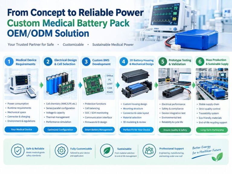
Dongguan Yizhan Electronics Technology Co., Ltd. provides custom lithium battery pack OEM/ODM solutions for medical equipment and other specialized applications.
The company’s battery development process can include cell selection, battery configuration, BMS design, 3D housing development, prototype production, testing, and mass manufacturing.
Custom BMS Design
Yi Zhan can discuss BMS requirements according to the battery configuration and equipment application.
Potential functions include:
- Schutz vor Überladung
- Schutz vor Überentladung
- Überstromschutz
- Kurzschlussschutz
- Temperaturschutz
- Zellausgleich
- Battery monitoring
- Communication interfaces
- Battery identification
The final BMS functions and parameters should be confirmed through technical review.
Custom Battery Structure
The battery housing and BMS layout can be developed according to the medical equipment’s available space.
The design process may include:
- Reviewing the equipment’s battery compartment
- Confirming the cell configuration
- Designing the BMS layout
- Reviewing connector and cable placement
- Developing the battery housing
- Preparing 3D design files
- Producing prototypes
This allows the battery and BMS to be developed together.
BMS and Equipment Communication
For OEM/ODM projects, Yi Zhan can discuss the communication requirements with the equipment manufacturer.
The communication design may involve:
- Battery data
- Fault information
- SOC
- Ladezustand
- Battery identification
- Kommunikationsschnittstelle
- Firmware requirements
The specific protocol and data format should be confirmed before development.
Prototype and Production Support
Yi Zhan supports custom battery pack development from technical requirements to production.
The project may include:
- Elektrotechnische Planung
- BMS design
- Konstruktion
- Prototypenfertigung
- Funktionsprüfung
- Qualitätsprüfung
- Production preparation
- Massenproduktion
This approach allows the equipment manufacturer to coordinate battery development with one supplier.
Medical Battery Applications
Custom BMS and battery pack solutions can be discussed for applications such as:
- Portable blood analyzers
- Patient monitoring equipment
- Medical carts
- Diagnostic instruments
- Tragbare medizinische Geräte
- Laborausstattung
- Ausrüstung für die Rehabilitation
- Emergency medical equipment
The final battery design depends on the equipment’s requirements and applicable standards.
15. FAQ: Custom BMS for Medical Battery Packs
What is a custom BMS?
A custom BMS is a battery management system developed or configured for a specific battery pack and application. It may include customized protection parameters, hardware, firmware, communication, and monitoring functions.
Can a BMS be customized for a portable medical device?
Yes. A BMS can be developed according to the device’s battery configuration, charging requirements, power demand, communication interface, and operating conditions.
What communication interfaces can a custom BMS support?
Depending on the design, a BMS may support SMBus, I²C, UART, CAN, or RS485. The appropriate interface depends on the equipment’s electrical and software architecture.
Why is SOC monitoring important?
SOC monitoring estimates the remaining battery charge. Medical equipment may use this information to display battery status, estimate runtime, or manage charging and maintenance.
Can the BMS communicate with the medical device?
Yes. A custom BMS may communicate battery voltage, current, temperature, SOC, fault status, and other information to the equipment’s main control system.
Does every medical battery pack need a custom BMS?
Not necessarily. Some applications may use a suitable existing BMS platform. However, a custom BMS may be required when the battery has specific protection, communication, mechanical, or monitoring requirements.
Can the BMS be integrated into a custom battery housing?
Yes. The BMS PCB, cell groups, insulation, wiring, connectors, and housing can be designed together to meet the battery’s mechanical and electrical requirements.
How is a medical battery BMS tested?
Testing may include electrical protection, cell balancing, temperature monitoring, communication, charging, discharge, and equipment-level validation. The exact test plan depends on the battery design and application.
Can Yi Zhan customize BMS parameters?
Yi Zhan can discuss BMS customization according to the battery configuration and equipment requirements. The available functions and parameter settings should be confirmed during the technical review.
How do I start a custom medical BMS project?
Provide the battery voltage, capacity, runtime, dimensions, charging requirements, peak current, communication interface, and application details. The supplier can then review the requirements and propose a suitable battery and BMS design.
Schlussfolgerung
A custom BMS is an important part of medical battery pack OEM/ODM development. It connects battery monitoring, protection, charging behavior, and equipment communication into one battery management system.
For medical equipment manufacturers, the BMS should be designed according to the actual battery configuration and the device’s operating requirements.
Important design considerations include cell voltage monitoring, overcharge and over-discharge protection, overcurrent protection, temperature monitoring, cell balancing, SOC estimation, communication, firmware management, and equipment-level validation.
The BMS should also be integrated with the battery housing, wiring, connectors, and manufacturing process.
A battery supplier with BMS development, mechanical design, prototype production, testing, and mass manufacturing capabilities can support the complete OEM/ODM development process.
When selecting a custom medical battery pack supplier, review the supplier’s technical capabilities, testing methods, documentation, and production process. A clear BMS specification and structured validation plan can help establish a battery solution that meets the requirements of the medical equipment.
 English
  Chinese
  Japanese
  German
  French
  Korean
