
An inspection robot uses battery power for movement, sensing, computing and communication. Some platforms also power lighting, thermal cameras, positioning equipment or mechanical actuators.
A custom battery specification should account for these loads and the conditions in which the robot operates. Voltage and capacity alone do not define whether a pack can support an inspection mission.
This guide explains the requirements OEMs should document when developing a battery pack for an inspection robot.
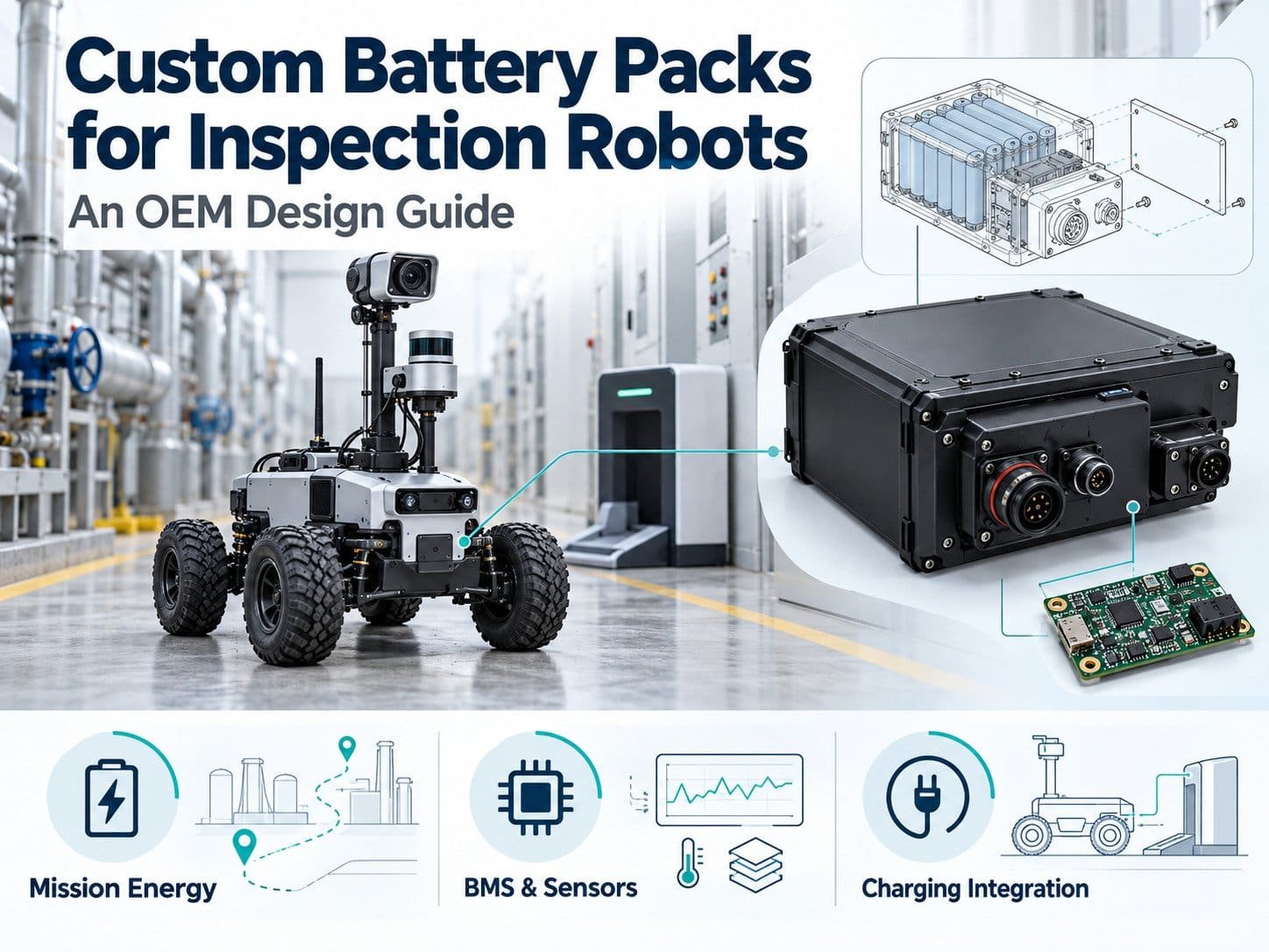
1. Define the Inspection Mission
Start with the robot’s actual work.
A robot inspecting an indoor facility may follow a scheduled route. An outdoor platform may encounter slopes, uneven surfaces and changing temperatures. A robot that stops to collect data has a different duty cycle from one that records while moving.
Document:
- Route distance and expected mission duration.
- Travel speed and stopping periods.
- Surface conditions and gradients.
- Payload and installed sensors.
- Inspection frequency.
- Available charging periods.
- Communication requirements.
- Return-to-dock and shutdown behavior.
Use measurements from a prototype where available. Record the conditions behind those measurements.
2. Separate the Electrical Loads
The drive motor is only one source of energy consumption.
Create a load list that includes the equipment powered by the battery.
| Load | Information to Record |
|---|---|
| Antriebsmotoren | Running current, starting current and transient duration |
| Computing hardware | Operating modes, startup demand and shutdown requirements |
| Kameras und Sensoren | Continuous or intermittent operation |
| Lighting | Power demand and activation schedule |
| Kommunikationsgeräte | Operating modes and transmission activity |
| Actuators | Current profile and frequency of use |
| Auxiliary electronics | Standby consumption and supply requirements |
Identify which loads operate together.
A robot may accelerate while its lighting, cameras and computer are active. The battery specification should reflect that combined demand.
3. Specify the Operating Voltage Range
Nominal voltage does not describe the entire battery voltage range.
Confirm the voltage accepted by the motor controller, DC-DC converters, computing hardware and other connected equipment.
The specification should define:
- Nominal pack voltage.
- Full-charge voltage.
- Normal discharge endpoint.
- Voltage behavior during load transients.
- BMS protection thresholds.
- Startup and shutdown sequencing.
If components require separate supply voltages, document the power distribution architecture and converter requirements.
Do not assume that equipment labeled for the same nominal voltage is electrically compatible.
4. Calculate Mission Energy
Estimate energy from the operating profile rather than from motor ratings alone.
For each operating stage:
Energy (Wh) = average battery power (W) × time (h)
Then add the energy used during the stages.
The following example illustrates the method.
| Mission Stage | Average Battery Power | Dauer | Calculated Energy |
|---|---|---|---|
| Travel | 200W | 2 hours | 400Wh |
| Stationary inspection | 80W | 1 hour | 80Wh |
| Waiting | 20W | 0.5 hours | 10Wh |
| Total | — | — | 490Wh |
These are illustrative figures, not specifications for a particular robot. They assume power is measured at the battery output.
The calculation does not establish the required nominal pack energy. The design must also account for the operating window, return reserve, temperature and battery condition.
Avoid counting the same loss or reserve twice.
5. Define Return-to-Dock Energy
An inspection robot needs an operating plan for the end of its mission.
The reserve should support the defined response, which may include:
- Returning to a charging station.
- Waiting for access to the dock.
- Attempting a permitted docking sequence.
- Sending a status message.
- Saving data.
- Entering a controlled shutdown.
Do not apply one fixed reserve percentage to every route.
Evaluate the energy needed under the project’s conditions, including location, load and route accessibility. Define what the robot should do if docking is unavailable.
State of Charge Is an Estimate
The displayed state of charge, or SOC, is not a direct measurement of mission completion capability.
Fuel-gauging methods may account for current, temperature, capacity and battery characteristics. The implementation requires validation with the selected battery.
Use SOC alongside relevant operating data and mission requirements. Do not rely on a displayed percentage as the sole protection mechanism.
6. Specify Continuous and Transient Current
Document the battery’s continuous current requirement and each defined transient.
For transients, record:
- Current magnitude.
- Duration.
- Repetition rate.
- Battery state of charge.
- Temperature.
- Permitted voltage drop.
Motor startup, turning, climbing and actuator operation may produce different load profiles.
The complete current path includes cells, interconnections, BMS components, protective devices, cables and connectors. A cell rating does not establish the current rating of the assembled pack.
Where the drive returns energy during braking, also define charge acceptance and DC-bus behavior.
7. Define BMS and Host Responsibilities
The battery and robot controller need defined responsibilities.
The BMS may monitor cell voltage, current and temperature, control charging and discharge, and report faults. The host manages tasks, movement and system shutdown according to its design.
Agree on:
- Normal operating limits.
- Warning thresholds.
- Protective disconnection conditions.
- Fault recovery.
- Sleep and wake-up behavior.
- Communication-loss response.
- Data recording.
Distinguish a warning that requests action from a condition requiring immediate protection.
Essential local battery protection should not depend solely on a functioning host connection.
8. Document Communication Requirements
Inspection robots may use CAN, RS485, UART or another specified interface.
The interface name alone does not establish compatibility. Obtain the host protocol and define:
- Message identifiers or register addresses.
- Units, scaling and byte order.
- Update intervals.
- Data validity.
- Timeouts.
- Fault codes.
- Command permissions.
- Firmware and protocol versions.
Useful battery information may include voltage, current, temperature, SOC, charge permission and discharge limits.
Define how the robot responds to missing or stale information. A communication fault should not silently leave the host using an old operating limit.
9. Plan Charging as Part of the Mission
The charging arrangement should match the operating schedule.
| Charging Arrangement | Items to Define |
|---|---|
| Automatisches Andocken | Alignment, contact engagement, charge permission and fault handling |
| Manual connection | Access, connector identification and charging procedure |
| Batteriewechsel | Retention, connection sequence and replacement verification |
| Charging between missions | Available time, charge profile and thermal conditions |
For automatic charging, define when power contacts become energized and how the system confirms a valid connection.
Review contact wear, contamination, moisture exposure and unsuccessful docking.
Charging time needs validation across the intended operating conditions. Capacity divided by charger current does not describe the complete charging process.
10. Account for the Inspection Environment
The battery enclosure must be specified for its installation.
Relevant conditions may include:
- Ambient temperature.
- Heat from onboard electronics.
- Rain and splash.
- Dust.
- Cleaning chemicals.
- Vibration and mechanical shock.
- Condensation.
- Storage periods.
If an ingress protection rating is required, identify the tested configuration, including connectors, covers and openings.
For locations with potentially explosive atmospheres, establish the equipment classification and applicable requirements separately. A general industrial battery assessment does not establish suitability for those locations.
11. Define Mounting and Service Access
Provide drawings showing the installation envelope, mounting points and cable routes.
Rückblick:
- Battery retention.
- Mass and location within the robot.
- Clearance around connectors.
- Cable strain relief.
- Access for inspection.
- Removal and replacement.
- Protection against unintended terminal contact.
For removable packs, test the handling procedure with the intended equipment. Record insertion, locking and connection requirements.
Do not assume that an enclosure dimension alone establishes fit.
12. Specify Service-Life Conditions
A cycle count should be accompanied by test conditions.
State the charging profile, discharge profile, depth of discharge, temperature and capacity-retention endpoint.
Calendar aging also matters when robots or spare batteries remain idle.
Define the application’s replacement criteria. These may include the ability to complete a mission, deliver current or maintain the required reserve.
Cell cycle-life data should not be presented as a verified service-life result for the complete robot battery.
13. Confirm Safety and Transport Requirements
Select standards according to the battery application, robot classification and destination market.
IEC 62619 is relevant to industrial secondary lithium batteries, but applicability must be confirmed for the specific inspection platform. Battery assessment does not establish conformity of the complete robot.
Transport requirements require separate review. UN38.3 documentation should correspond to the battery design being shipped, together with the applicable packaging and shipping arrangements.
Request a documented compliance plan rather than assuming one certificate covers every application.
14. Validate the Battery in the Robot
Test the battery with the intended drive, sensors, computer, charger and software configuration.
| Test Area | Verification |
|---|---|
| Mission energy | Consumption across the defined route and inspection sequence |
| Transient loads | Current, voltage drop and protection behavior |
| Return reserve | Defined response at the end of the mission |
| Aufladen | Docking, charge control and fault handling |
| Thermal operation | Cell and component temperatures |
| Kommunikation | Interpretation, timing and data-loss behavior |
| Shutdown | Data handling and controlled power-down |
| Mechanical installation | Retention, cables and service access |
| Umgebungsbedingungen | Exposure defined by the project |
Set acceptance criteria before testing. Record hardware revisions, firmware, payload, route and environmental conditions.
15. OEM Battery RFQ Checklist
Include the following in an inspection robot battery inquiry:
- Robot description and intended environment.
- Mission profile and measured loads.
- Voltage range and energy requirement.
- Continuous and transient current.
- Return reserve and shutdown requirements.
- Charging arrangement.
- Communication specification.
- Installation drawing and mass limit.
- Environmental exposure.
- Service-life conditions.
- Required documentation.
- Sample quantities and validation responsibilities.
Mark unresolved items as open requirements.
Häufig gestellte Fragen
Can an AGV Battery Be Used in an Inspection Robot?
Possibly, if its electrical, mechanical, charging and communication characteristics match the robot. The product label alone does not establish compatibility.
How Much Battery Reserve Does a Robot Need?
Define it from the return route, docking process, standby loads and shutdown requirements. A universal percentage does not represent every mission.
Can a Robot Charge During a Short Stop?
That depends on the charging window, battery limits, temperature and dock design. Validate the complete charging sequence.
Does an IP Rating Establish Outdoor Suitability?
It addresses a defined ingress test. Outdoor suitability also requires consideration of temperature, condensation, mechanical exposure and other project conditions.
What Should Be Approved Before Production?
Approve the construction, cell model, BMS settings, firmware, interfaces, charging configuration, validation results and required documents.
Preparing an Inspection Robot Battery Project
Begin with the inspection mission and measured load profile. Define the battery’s role in operation, return-to-dock behavior, charging and shutdown.
Use those requirements to establish the pack specification, then validate it in the intended robot configuration before production.
 English
 Chinese
 Japanese
 German
 French
 Korean

