
Cells connected in series can develop differences in charge state during operation and storage. Battery cell balancing manages these differences within the limits of the selected hardware and control strategy.
For an OEM project, “BMS with balancing” is not a complete requirement. The specification should explain when balancing operates, how much current it handles and how its behavior will be verified.
This guide explains balancing methods, their limitations and the information manufacturers should document.
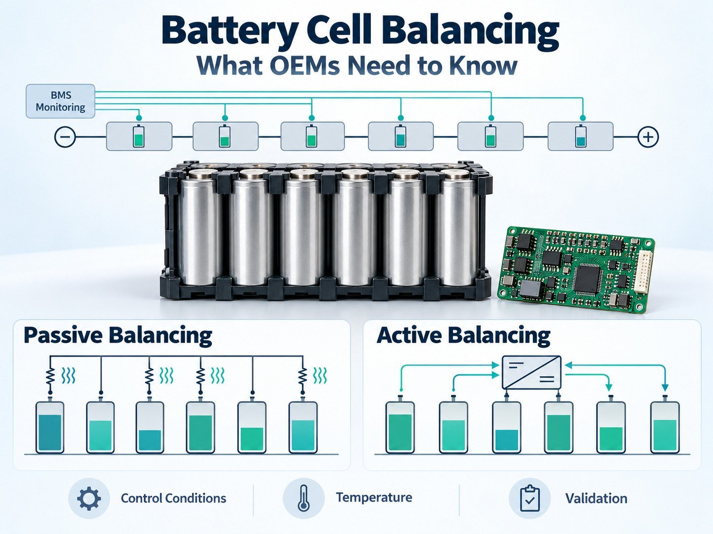
What Is Battery Cell Balancing?
Cell balancing adjusts charge distribution among the series-connected cells or cell groups in a battery.
In a series string, the same pack current passes through each series position. Differences in capacity, self-discharge, temperature and initial charge state can cause individual positions to reach an operating limit at different times.
The BMS may use cell voltage, estimated state of charge or other defined information to decide when balancing is needed.
Balancing does not replace cell monitoring or protection.
Cells and Parallel Groups
In a pack containing parallel groups connected in series, the BMS commonly monitors each parallel group as one voltage measurement.
For example, a 10S4P pack has ten series positions, each containing four parallel cells.
A balancing circuit connected across those positions acts on the parallel groups. It does not necessarily monitor or diagnose each cell within a group.
The specification should identify what the BMS measures and balances.
Why Differences Develop
Charge-state differences can arise from:
- Initial cell conditions.
- Capacity variation.
- Self-discharge.
- Temperature distribution.
- Unequal drain from connected circuits.
- Aging.
- Measurement or connection faults.
Not every voltage difference indicates a need for balancing.
A sensing-wire fault, contact problem or damaged cell requires investigation. Balancing should not be used to conceal an unresolved fault.
Passive Cell Balancing
Passive balancing uses a controlled discharge path, typically involving resistors, across selected cells or groups. Energy removed through that path becomes heat.
The circuit’s operating current and temperature depend on its components and control method. Analog Devices describes the principle in its technical article on passive balancing.
An OEM specification should identify:
- Balancing current and its operating conditions.
- Permitted cell-voltage range.
- Temperature restrictions.
- Number of channels that can operate together.
- Duty cycle.
- Start and stop conditions.
Do not assume that balancing runs continuously whenever the pack is connected to a charger.
Active Cell Balancing
Active balancing transfers energy through a controlled conversion circuit. Depending on the architecture, energy may move between cells, groups or other parts of the battery system.
Implementations can use components such as inductors, transformers or capacitors. The topology determines the available transfer paths.
The specification should state:
- Transfer topology.
- Source and destination paths.
- Transfer current.
- Operating voltage range.
- Control method.
- Thermal limits.
- Fault response.
The term “active balancing” alone does not establish runtime, service life or suitability for an application.
Passive and Active Balancing: Design Characteristics
| Artikel | Passive Balancing | Active Balancing |
|---|---|---|
| Charge management | Removes charge through a discharge path | Transfers energy through a conversion circuit |
| Energy handling | Dissipates energy as heat | Transfers energy with conversion losses |
| Hardware | Switching paths and discharge components | Switching and energy-transfer components |
| Parameters to define | Current, duty cycle and thermal limits | Transfer paths, current and thermal limits |
| Validation | Operation within defined conditions | Operation within defined conditions |
Selection should follow the battery’s charge imbalance, available operating time, installation conditions and system requirements.
Cell Voltage Is Not the Same as State of Charge
A voltage reading depends on conditions including current, temperature, resistance and time since charging or discharging.
Equal terminal voltages do not establish identical capacity or identical state of charge.
This matters when the voltage–state-of-charge relationship contains a flat region, as can occur with LFP cells.
For a voltage-based strategy, define the measurement conditions and the region in which balancing is permitted. Do not use a voltage-difference threshold without considering measurement uncertainty and operating conditions.
When Does Balancing Operate?
Balancing may be permitted during charging, rest or other operating states, depending on the design.
The BMS can apply conditions such as:
- A defined cell-voltage threshold.
- A voltage-difference threshold.
- Temperature limits.
- Current limits.
- A timer.
- A host command.
Operation is implementation-specific. For example, TI’s BQ769x2 application note describes balancing control options and measurement considerations for that device family. These settings should not be applied to unrelated products without review.
Ask the supplier to document the actual behavior of the selected BMS.
Balancing Current and Available Time
The balancing function must have time to address the expected charge difference.
A preliminary calculation is:
Balancing time ≈ charge difference ÷ effective balancing current
For example, an assumed charge difference of 0.1Ah and an effective balancing current of 0.05A give an idealized time of two hours.
This calculation excludes effects such as switching duty cycle, changing voltage, temperature restrictions and interruptions.
It is a planning example, not a guaranteed balancing time.
Use effective operating current rather than a component’s headline rating. Confirm how often the system reaches conditions in which balancing is allowed.
Charging Behavior and Balancing
A battery that receives short charging sessions may not regularly reach its balancing activation conditions.
That does not automatically establish a design fault. It means the balancing strategy and charging schedule need to be evaluated together.
Document:
- Charging profile.
- Charge termination.
- Balancing activation conditions.
- Available balancing time.
- Behavior after charger disconnection.
- Sleep-mode restrictions.
Do not instruct users to leave a battery connected indefinitely to complete balancing. Charging instructions must follow the approved battery–charger design.
What Balancing Cannot Do
Balancing cannot:
- Restore a damaged cell.
- Reverse aging.
- Repair an electrical connection.
- Correct a sensor fault.
- Establish that unmatched cells are suitable for assembly.
- Guarantee identical capacity among cells.
- Replace overvoltage or undervoltage protection.
If the same series position repeatedly reaches a limit, investigate the cause.
Review capacity, resistance, self-discharge, sensing, temperature and connection records before changing balancing settings.
What OEMs Should Specify
| Parameter | Information to Document |
|---|---|
| Batteriekonfiguration | Cell model, chemistry and series–parallel arrangement |
| Balancing level | Individual cells or parallel groups |
| Method | Passive or active, including topology |
| Control basis | Voltage, estimated charge state or another defined input |
| Activation | Thresholds, operating states and delays |
| Aktuell | Expected value and operating conditions |
| Scheduling | Duty cycle and simultaneous-channel limits |
| Temperatur | Measurement locations and operating restrictions |
| Fault response | Detection, stop conditions and reporting |
| Records | Status data, events and configuration version |
Avoid choosing thresholds by copying another battery’s settings.
Thermal Considerations
Balancing components generate heat. The design must account for that heat within the installed enclosure.
Assess:
- Component temperature.
- PCB layout.
- Airflow and enclosure conditions.
- Heat from adjacent components.
- Temperature sensing.
- Simultaneous-channel operation.
Measurements made on an open development board do not establish temperatures inside a closed production pack.
Measurement and Diagnostics
Balancing can interact with the voltage-measurement circuit. The effect depends on the monitor, wiring and timing.
Follow the selected component’s design guidance and verify readings against the approved measurement method.
Useful diagnostic information can include:
- Cell or group voltages.
- Pack current.
- Temperatures.
- Active balancing channels.
- Balancing duration.
- Fault events.
- Hardware and firmware versions.
Record whether readings were taken during charge, discharge, rest or balancing.
Validation Before Production
Define acceptance criteria before testing.
| Test Area | Verification |
|---|---|
| Activation | Balancing starts under the specified conditions |
| Stop behavior | Balancing stops at defined limits |
| Aktuell | Actual current matches the approved design |
| Temperatur | Components remain within specified limits |
| Measurement | Readings meet the required accuracy |
| Scheduling | Channel and duty-cycle rules operate as intended |
| Fault handling | Defined faults produce the required response |
| Sleep and wake-up | Behavior matches the specification |
| Charging integration | Operation matches the approved charging schedule |
Use controlled laboratory procedures for fault simulation. Do not create an imbalance by manually charging or discharging individual cells in an assembled pack outside an approved process.
Production and Change Control
Record the balancing-related components, firmware and settings in the approved design.
Review changes to:
- Cells.
- Resistors or transfer components.
- Monitoring circuits.
- PCB layout.
- Firmware.
- Activation thresholds.
- Temperature limits.
Determine whether the change requires testing or an update to the technical documents.
Häufig gestellte Fragen
Does Every BMS Include Balancing?
No. Confirm the features of the selected hardware and firmware.
Does Balancing Mean Every Cell Has the Same Capacity?
No. Balancing manages charge distribution. It does not make cell capacities identical.
Is Active Balancing Required for Every Custom Pack?
No. Selection depends on the application and documented requirements.
Can Voltage Difference Alone Identify a Faulty Cell?
No. Review the operating conditions, measurement system and other evidence.
Does Balancing Establish Battery Life?
No. A life claim requires test evidence and stated conditions. The presence of balancing does not establish a cycle count or service period.
Can Balancing Settings Be Changed in the Field?
Only under the approved configuration and service process. Changes can affect thermal behavior, measurement and operation.
Preparing the Balancing Specification
Define the charge differences the system is expected to manage, the operating conditions and the available balancing time.
Document the method, limits and fault behavior. Validate the function with the intended cells, BMS, charger and enclosure before production.


 English
 Chinese
 Japanese
 German
 French
 Korean

