
A user-replaceable battery pack allows operators to remove a depleted battery and install a charged replacement without replacing the entire device. This battery architecture is increasingly relevant to portable electronics, medical equipment, industrial instruments, handheld terminals, inspection devices and other professional equipment.
However, designing a reliable replaceable lithium battery pack involves much more than choosing a cell with the required capacity.
The battery must be designed around the complete device architecture, including voltage, current, runtime, BMS protection, charging, connectors, mechanical retention, thermal management, communication, environmental conditions and applicable regulations.
For OEM and ODM equipment manufacturers, these requirements should be considered during the early product-development stage.
This guide explains the key considerations for designing user-replaceable battery packs for portable, medical and industrial devices, from battery chemistry and BMS selection to mechanical design, testing and regulatory compliance.
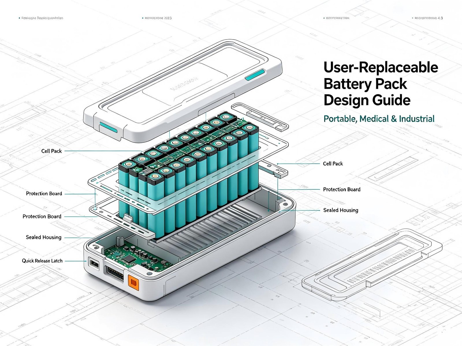
What Is a User-Replaceable Battery Pack?
A user-replaceable battery pack is a rechargeable battery assembly designed to be removed and replaced by the intended user during the service life of the equipment.
Unlike a permanently integrated battery, a replaceable battery normally combines several components into one engineered module:
- Lithium-ion or LiFePO4 battery cells
- バッテリー管理システム(BMS)
- Protection circuitry
- 電源コネクタ
- Communication contacts
- 温度センサー
- バッテリーケース
- Mechanical positioning structure
- ロック機構
- Identification components
- 充電インターフェース
The battery may use a slide-in, plug-in, cartridge, latch or screw-retained structure depending on the equipment design.
The goal is not simply to make the battery removable. The complete system should ensure that the battery remains electrically stable, mechanically secure and thermally controlled during repeated replacement.
For professional equipment, the battery and host device should therefore be designed as an integrated system.
Why Use a Replaceable Battery Pack?
A user-replaceable battery architecture can provide several practical advantages for equipment manufacturers and end users.
1. Reduce Equipment Downtime
A depleted battery can be replaced with a charged battery instead of waiting for the device to recharge.
例えば、こうだ:
Depleted battery → Remove battery → Install charged battery → Resume operation
This approach can be useful for:
- Portable medical equipment
- Industrial handheld terminals
- Barcode scanners
- Field-service equipment
- Inspection instruments
- Portable measurement devices
- Professional communication equipment
- Industrial tablets
- Portable diagnostic equipment
For equipment operating across multiple shifts, spare batteries can also be prepared in advance.
2. Extend Equipment Serviceability
Lithium batteries naturally lose available capacity as they age.
If the battery is permanently integrated into a device, battery degradation can eventually become a service issue for the entire product.
A replaceable battery architecture separates the battery from the main equipment.
This allows the equipment to remain in service while the battery pack is replaced when its useful service life has been reached.
This can be particularly useful for industrial equipment with long service cycles.
3. Support Fleet Battery Management
Industrial customers may operate dozens or hundreds of identical devices.
A standardized replaceable battery can support a battery-pool model:
Equipment → Used Battery → Charging Station → Ready Battery
Operators can replace depleted batteries during shift changes or maintenance intervals.
The battery fleet can also be managed according to:
- 充電状態
- バッテリーの使用年数
- 循環棚卸
- Battery health
- Inspection status
- Serial number
A smart BMS can provide additional information to the host system when communication is required.
Start Battery Design With the Host Device
One of the most common battery-development mistakes is selecting a battery first and attempting to fit it into the equipment afterward.
A better approach is to define the host device requirements before selecting cells.
The battery manufacturer should normally receive information such as:
| パラメータ | Design Information |
|---|---|
| 公称電圧 | V |
| 動作電圧範囲 | V |
| 定員 | mAh / Ah |
| 平均電流 | A |
| 連続電流 | A |
| ピーク電流 | A |
| 実行時間 | 営業時間 |
| 充電電流 | A |
| 充電電圧 | V |
| バッテリー寸法 | 長さ × 幅 × 高さ |
| Maximum weight | kg |
| 動作温度 | °C |
| 充電温度 | °C |
| 保存温度 | °C |
| コミュニケーション | SMBus / CAN / UART / I²C / Custom |
| コネクタ | Power + signal contacts |
| Environmental requirement | IP rating, vibration, shock |
| Expected cycle life | Cycles |
| ターゲット市場 | US / EU / Japan / Korea / etc. |
This information provides the foundation for cell selection, BMS design and mechanical development.
How to Select Battery Chemistry
Battery chemistry affects energy density, voltage characteristics, cycle life, thermal behavior, weight and overall pack design.
Two common lithium battery chemistries for custom battery packs are NMC lithium-ion そして LiFePO4.
NMC Lithium-Ion Battery Packs
NMC cells may be considered when the equipment has tight space or weight constraints.
Potential advantages include:
- 高エネルギー密度
- Compact battery dimensions
- Lower pack weight for a given energy requirement
- Suitable for many portable devices
NMC-based battery packs can be used in applications such as:
- Portable instruments
- Handheld equipment
- Professional electronics
- Portable medical equipment
- Industrial terminals
The actual cell selection should still be based on current demand, operating temperature, cycle requirements and certification requirements.
LiFePO4 Battery Packs
LiFePO4 can be considered when cycle life and thermal characteristics are important and the application can accommodate its relatively larger size and weight for the same energy requirement.
主な用途としては、次のようなものが挙げられます:
- 産業機器
- Portable power systems
- AGV and AMR equipment
- 医療用カート
- バックアップ電源システム
- Professional equipment
- Energy-intensive devices
There is no single battery chemistry that is suitable for every application.
The correct choice should balance:
Energy density + power + cycle life + temperature + dimensions + weight + safety requirements + cost
Calculate Battery Capacity From Actual Power Consumption
Battery capacity should be calculated from the equipment’s actual energy consumption rather than selected solely from a nominal Ah value.
基本的な計算式は次のとおりです:
必要エネルギー = 平均出力 × 稼働時間
For a device consuming 20 W for five hours:
20 W × 5 h = 100 Wh
If the estimated system efficiency is 90%:
100 Wh ÷ 0.90 ≈ 111 Wh
The final battery design may require additional consideration for:
- バッテリーの経年劣化
- 低温動作
- BMS cutoff thresholds
- ピーク電流
- Manufacturing tolerance
- Remaining energy reserve
- Actual duty cycle
The battery’s usable energy may therefore be more important than its nominal capacity.
BMS Design for User-Replaceable Battery Packs
The Battery Management System is a critical part of a rechargeable lithium battery pack.
Depending on the application, the BMS can provide:
- 過充電保護
- 過放電保護
- 過電流保護
- 短絡保護
- 過熱保護
- 低温保護機能
- セルバランシング
- 電圧監視
- 電流の監視
- SOC推定
- SOH推定
- 故障検出
- バッテリーの識別
- コミュニケーション
The exact protection thresholds should be matched to the selected cells and host equipment.
Smart BMS Communication
Professional equipment may require the battery to communicate with the host controller.
利用可能な通信インターフェースには、以下のものがあります:
- SMBus
- I²C
- UART
- CAN
- Custom communication protocols
Battery information may include:
- パック電圧
- Pack current
- 細胞電位
- 温度
- 充電状態
- 健康状態
- 循環棚卸
- Battery serial number
- 障害状況
This can help the equipment monitor battery condition and manage battery operation.
For OEM projects, the BMS communication protocol should be defined before finalizing the battery electronics.
Connector Design for Replaceable Battery Packs
The battery connector is an important part of a removable battery system.
A replaceable battery can experience repeated insertion and removal throughout its service life. Connector selection should therefore consider:
- 定格電流
- 定格電圧
- Contact resistance
- Insertion and removal cycles
- Mechanical strength
- Contact protection
- 環境条件
- コネクタの寸法
A battery may contain separate contacts for:
Positive + Negative + Communication + Temperature + Identification
The exact pin configuration depends on the equipment architecture.
Preventing Reverse Installation
Mechanical keying and polarized connectors can help prevent incorrect installation.
Possible design features include:
- Keyed housing
- Asymmetric battery shape
- Guide rails
- Polarized connector
- Mechanical latch
- Visual installation indicators
The mechanical structure should make incorrect installation difficult rather than relying entirely on warning labels.
Inrush Current and Anti-Spark Design
When a battery is connected to a device containing large input capacitors, an inrush current can occur.
In higher-power applications, this may result in:
- Electrical arcing
- Connector wear
- Contact damage
- EMI problems
- BMS protection triggering
A suitable battery architecture may therefore incorporate:
- Pre-charge circuitry
- Controlled MOSFET switching
- Current-limiting circuitry
- Soft-start functionality
The appropriate solution depends on the battery voltage, load characteristics and host-device power architecture.
This should be evaluated during prototype testing rather than after mass production begins.
Mechanical Design of a User-Replaceable Battery
A removable battery needs to withstand repeated installation and removal while remaining securely connected during normal operation.
Mechanical Positioning
Guide structures should ensure that the battery reaches a repeatable position before the electrical contacts engage.
Mechanical Locking
A latch or locking structure can help prevent accidental battery removal during:
- Normal operation
- Movement
- 振動
- 衝撃
- 交通
Shock and Vibration
Industrial equipment may experience repeated vibration or accidental drops.
The battery housing and internal cell assembly should therefore be evaluated according to the actual operating environment.
Potential design considerations include:
- Cell fixation
- 住宅市場の堅調さ
- Connector support
- Internal insulation
- Shock-absorbing structures
- ケーブルの配線
A battery that fits the enclosure perfectly but moves internally during vibration is not a finished battery design.
熱管理
Battery temperature affects performance, charging behavior, safety and service life.
Thermal design should consider:
- Normal operating load
- 最大連続電流
- ピーク電流
- 充電
- 周囲温度が高い
- Low ambient temperature
- 連続運転
- Heat generated by adjacent electronics
Possible thermal-management measures include:
- 温度センサー
- Thermal interface materials
- Heat-spreading structures
- セル間隔
- BMS temperature protection
- 充電温度の制限
- Enclosure thermal design
For handheld medical and industrial equipment, external battery temperature should also be considered because the battery may be touched directly by the operator.
Designing User-Replaceable Batteries for Medical Equipment
Medical equipment has additional requirements because battery performance can affect equipment availability and, depending on the application, patient-related operation.
Potential medical applications include:
- 患者用モニター
- Portable ultrasound systems
- Diagnostic instruments
- 医療用カート
- Portable monitoring equipment
- Dental equipment
- Portable professional medical devices
The battery should be considered as part of the overall medical-device design and risk-management process.
IEC 62133-2 specifies safety requirements and tests for portable sealed secondary lithium cells and batteries. The standard is also recognized by the U.S. FDA as a consensus standard relevant to medical-device submissions.
Medical battery designs may therefore need to consider:
- 安定した電圧出力
- Reliable protection
- Accurate SOC information
- 温度モニタリング
- バッテリーの識別
- Fault reporting
- 充電制御
- トレーサビリティ
- Cycle-life requirements
- Applicable medical-device standards
Hot-Swap Battery Design
Some professional medical equipment may require continuous operation.
A hot-swap architecture can use multiple battery inputs or another backup power source so that one battery can be replaced while the equipment remains powered, where permitted by the system architecture.
A simplified architecture can be represented as:
Battery A + Battery B → Power Management → Medical Equipment
When Battery A needs replacement, the system can transfer the load to Battery B before Battery A is removed.
The actual implementation requires system-level validation and depends on the equipment’s safety requirements.
Designing Batteries for Industrial Equipment
Industrial applications often prioritize durability, runtime and serviceability.
代表的な用途は以下の通り:
- Industrial handheld terminals
- Barcode scanners
- Inspection instruments
- Portable measurement equipment
- Industrial tablets
- Field-service equipment
- Portable control systems
- Communication terminals
Industrial battery packs may encounter:
- ダスト
- 水分
- 振動
- 衝撃
- Frequent battery replacement
- 温度変動
- Long operating shifts
The battery enclosure, connector and internal assembly should therefore be designed according to the actual operating environment.
Where environmental protection is required, the complete battery enclosure and interface design may need to be evaluated for the relevant IP rating.
User-Replaceable Batteries and EU Battery Regulation
For manufacturers selling products in the European Union, battery removability and replaceability should be considered during product development.
Regulation (EU) 2023/1542 contains requirements concerning the removability and replaceability of portable batteries incorporated into products.
Article 11 establishes requirements for portable batteries to be removable and replaceable by the end user during the product’s lifetime, subject to specified conditions, exceptions and derogations. These requirements apply from 18 February 2027.
The regulation also addresses the tools and procedures that may be used for battery removal and replacement. Certain exceptions apply, including specific situations involving professional medical equipment and other products where permanent connection may be justified by safety or data-integrity considerations.
The European Commission has also published guidance intended to facilitate a harmonized application of the removability and replaceability provisions.
What Does This Mean for Battery Design?
For products intended for the EU market, manufacturers should evaluate battery architecture early.
Questions include:
- Is the product covered by the portable-battery requirements?
- Can the battery be removed safely?
- Can the end user replace it?
- Are specialized tools required?
- Does the product fall under an applicable exception?
- Does battery replacement create an electrical or mechanical safety risk?
- Can the battery be replaced without damaging the product?
This assessment should be performed together with the product’s regulatory and engineering teams.
Battery Housing and Enclosure Design
The battery housing provides more than cosmetic protection.
It may need to provide:
- 機械的保護
- 電気絶縁
- Cell positioning
- Connector support
- Environmental protection
- 熱管理
- User handling surfaces
- バッテリーの識別
Common housing materials include engineering plastics such as ABS and PC, depending on the required mechanical, thermal and environmental characteristics.
Housing design should also consider manufacturing method.
Possible approaches include:
- Injection molding
- CNC-machined prototypes
- Screwed enclosures
- 超音波溶接
- Custom molded battery cases
For OEM projects, prototype housings can be developed before the final production tooling is released.
Battery Identification and Traceability
Professional battery packs may require identification and traceability functions.
The battery can store or communicate information such as:
- バッテリーの型番
- Serial number
- Manufacturing date
- Production batch
- 公称容量
- Firmware version
- 循環棚卸
- 健康状態
- Fault history
Battery identification can help the equipment recognize compatible battery models and support maintenance management.
For industrial fleets, serial-number tracking can also help manufacturers monitor battery replacement and service history.
Testing User-Replaceable Battery Packs
Battery testing should include both component-level testing and system-level validation.
電気試験
Typical tests include:
- キャパシティ・テスト
- 電圧試験
- 内部抵抗試験
- Charge testing
- Discharge testing
- Continuous-current testing
- Peak-current testing
- 過充電保護
- 過放電保護
- 短絡保護
機械的試験
Depending on the application:
- 落下試験
- 振動試験
- Mechanical shock testing
- Housing strength testing
- Connector insertion/removal testing
IEC 62133-2 includes mechanical and electrical safety tests applicable to portable rechargeable lithium battery systems.
環境試験
Depending on the equipment’s operating environment:
- 高温試験
- 低温試験
- 温度サイクル試験
- Humidity testing
- Dust testing
- Water-ingress testing
System-Level Testing
The battery should also be evaluated while connected to the actual equipment.
This can identify issues such as:
- Unexpected shutdown
- 電圧降下
- Communication failure
- Connector instability
- Excessive inrush current
- Thermal problems
- Incorrect SOC reporting
- Unwanted BMS protection activation
System-level validation is particularly important for custom OEM batteries because the battery and host device are designed as a combined power system.
Battery Compliance and Certification
The applicable compliance requirements depend on the battery design, host product, destination market and intended application.
Potential requirements may include:
| 要件 | 代表的なアプリケーション |
|---|---|
| IEC 62133-2 | Portable rechargeable lithium batteries |
| 国連 38.3 | Lithium battery transportation |
| UL規格 | Applicable US battery/product applications |
| EUバッテリー規制 | Batteries and products placed on the EU market |
| CE関連の要件 | Applicable European products |
| RoHS | Applicable electrical/electronic products |
| Medical-device requirements | Applicable medical equipment |
The exact certification route should be determined from the final battery and equipment configuration.
Certification planning should start during the engineering stage because changing the cell, BMS or mechanical construction late in development can affect testing and certification.
User-Replaceable Battery Pack OEM/ODM Development Process
For custom battery projects, a structured development process can reduce design iterations.
Step 1: Define Battery Requirements
The equipment manufacturer provides:
- 電圧
- 定員
- 現在
- 実行時間
- 寸法
- 重量
- Connector requirements
- 通信プロトコル
- 充電方法
- 動作温度
- 環境要件
- ターゲット市場
Step 2: Select Cells
The battery manufacturer evaluates appropriate cell chemistry, cell format and cell model.
The selection should consider:
- エネルギー密度
- Discharge capability
- サイクル寿命
- Temperature performance
- 外形寸法
- Availability
- コスト
Step 3: Design the BMS
The BMS is developed according to:
- セルの構成
- 電圧
- 現在
- 保護要件
- 温度範囲
- 通信要件
Step 4: Develop the Battery Housing
Mechanical engineering integrates:
- 細胞の配列
- ビーエムエス
- コネクタ
- ロック機構
- 取り付け位置
- Thermal structures
- User interface
Step 5: Build Prototypes
Engineering samples can be used for:
- Mechanical fit testing
- 電気試験
- Charging testing
- Runtime testing
- 通信テスト
Step 6: Design Verification
The battery is evaluated under expected operating and abnormal conditions.
Step 7: Certification
Applicable standards and transportation requirements are addressed according to the target market.
Step 8: Mass Production
After validation and approval, the battery can enter controlled mass production with appropriate inspection, testing and traceability procedures.
Common User-Replaceable Battery Design Mistakes
1. Selecting the Battery Based Only on Capacity
Capacity alone does not determine whether a battery is suitable.
Voltage, current, temperature, cell characteristics and BMS behavior must also match the host device.
2. Ignoring Connector Durability
A removable battery may experience hundreds or thousands of insertion cycles.
Connector life should therefore be included in the specification.
3. Treating the BMS as a Standard Add-On
Different applications may require different protection parameters and communication functions.
The BMS should be designed around the cell configuration and equipment requirements.
4. Designing the Battery Too Late
If the battery is designed only after the host enclosure has been finalized, there may be insufficient space for the required capacity, connector or thermal structure.
Battery development should run in parallel with mechanical and electrical product development.
5. Testing Only the Battery
A battery can pass standalone tests but still cause problems when connected to the actual device.
System-level testing is essential.
6. Ignoring Future Regulatory Requirements
For products intended for the EU market, manufacturers should evaluate the removability and replaceability requirements of Regulation (EU) 2023/1542 during the design stage.
User-Replaceable Battery Pack Design Checklist
Before approving a battery design, the engineering team can review the following checklist.
電気
- Nominal voltage confirmed
- Operating voltage range confirmed
- Capacity calculated
- Continuous current confirmed
- Peak current confirmed
- Charging voltage confirmed
- Charging current confirmed
- BMS protection parameters defined
機械
- Battery dimensions confirmed
- Weight confirmed
- Connector position confirmed
- Mechanical latch defined
- Battery insertion direction defined
- Reverse installation prevented
- Drop and vibration requirements defined
Thermal
- Operating temperature defined
- Charging temperature defined
- Temperature sensors included
- Heat generation evaluated
- Thermal path evaluated
コミュニケーション
- Communication protocol defined
- SOC reporting defined
- SOH reporting defined
- Battery identification defined
- Fault reporting defined
Regulatory
- Applicable battery standards identified
- UN 38.3 requirements considered
- Target-market requirements identified
- Medical-device requirements considered where applicable
- EU Battery Regulation reviewed where applicable
How to Choose a Custom Battery Pack Manufacturer
When sourcing a custom battery pack, equipment manufacturers should evaluate more than the supplier’s quoted capacity and unit price.
A suitable OEM/ODM partner should be able to participate in the complete battery-development process.
Key capabilities may include:
細胞の選択
The manufacturer should be able to evaluate cell options according to the application’s voltage, current, capacity, dimensions, temperature and lifecycle requirements.
BMS開発
The supplier should be able to customize BMS protection parameters and communication functions when required.
Mechanical Engineering
The supplier should support battery housing and connector integration rather than supplying only loose cells or a standard battery pack.
試作開発
The supplier should have a defined process for engineering samples and design verification.
テスト
Battery testing should cover the relevant electrical, mechanical and environmental requirements.
認証サポート
The manufacturer should understand the certification and transportation requirements relevant to the target market.
For OEM/ODM projects, a battery supplier capable of coordinating cells, BMS, mechanical design, connectors, testing and production can reduce communication between multiple vendors.
Conclusion: Design the Battery as Part of the Product
A user-replaceable battery pack is not simply a removable lithium battery.
It is a complete electromechanical system that connects the battery cells with the host device.
Successful battery design requires coordination between:
Cell Selection → Capacity → BMS → Connector → Mechanical Structure → Thermal Management → Communication → Testing → Compliance
For portable equipment, the focus may be compact size and energy density.
For medical equipment, predictable operation, protection, monitoring and applicable regulatory requirements can become more important.
For industrial equipment, serviceability, mechanical durability, environmental protection and operating time may receive greater attention.
For products intended for the European market, battery removability and replaceability should also be evaluated early in the product-development process in light of Regulation (EU) 2023/1542.
For equipment manufacturers developing a custom battery, the most efficient approach is generally to define the battery together with the host device rather than selecting an off-the-shelf battery at the end of the product-development cycle.
A well-designed user-replaceable battery should be electrically compatible, mechanically secure, thermally controlled, serviceable and validated for its intended operating environment.
For OEM and ODM projects, manufacturers can provide the equipment’s voltage, capacity, current, dimensions, runtime, connector and application requirements to a battery engineering team. These parameters can then be used to develop a customized lithium battery pack and BMS solution.
 English
  Chinese
  Japanese
  German
  French
  Korean
