
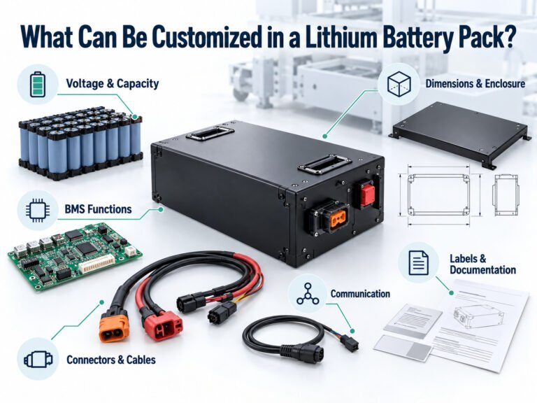
A custom battery pack is more than a group of battery cells connected together. For industrial robots, AGVs, AMRs, 医療機器, portable equipment, power tools, e-bikes, drones, and energy storage systems, the battery is an integrated power system that must match the electrical, mechanical, thermal, communication, safety, and operating requirements of the final product.
For OEM and ODM customers, a structured battery development process can reduce design changes, prototype failures, certification issues, and production risks.
From the initial technical requirements to cell selection, BMS development, mechanical design, prototype testing, certification, pilot production, and mass production, every stage has an impact on the final battery pack.
This guide explains the key stages of a custom battery pack development process and the information manufacturers and product engineers should evaluate before moving into production.
1. Start With the Application Requirements
The first step in custom battery pack design is understanding how the battery will actually be used.
A battery specification should not be created only from the required voltage and capacity. The battery manufacturer needs to understand the complete operating profile of the equipment.
Important information includes:
- Application and equipment type
- 公称系統電圧
- 動作電圧範囲
- 平均電流
- 最大連続電流
- ピーク電流
- ピーク電流の持続時間
- 平均消費電力
- Operating hours per cycle
- Daily operating cycles
- 充電方法
- Charging voltage and current
- Required charging time
- 動作温度
- 充電温度
- 保存温度
- バッテリー設置スペース
- 重量制限
- 通信要件
- Waterproof or dustproof requirements
- Expected cycle life
- Target service life
- Destination market
- Applicable certification requirements
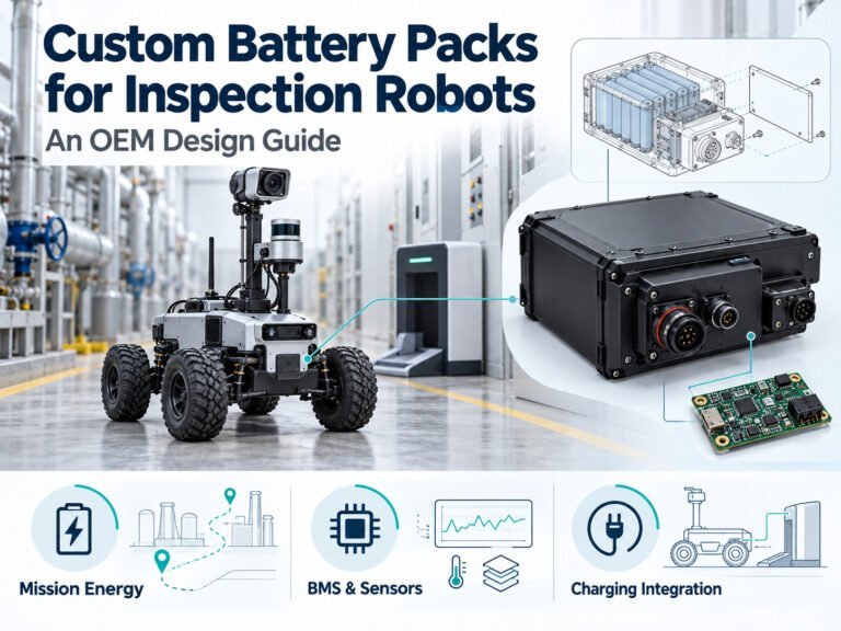
For example, an industrial robot battery may need high discharge capability, vibration resistance, communication with the robot controller, and reliable operation over long working cycles.
A battery for medical equipment may place greater emphasis on stable power delivery, accurate state-of-charge information, protection functions, reliability, and applicable regulatory requirements.
This is why battery design should start with the application rather than with a particular cell model.
2. Define Voltage, Capacity, and Energy Requirements
Once the operating conditions are understood, the battery manufacturer can establish the basic electrical configuration.
Lithium battery packs are commonly configured by connecting cells in series and parallel.
For example, a configuration described as 13S4P contains:
- 13 cells or cell groups connected in series
- 4 cells connected in parallel in each group
- 52 individual cells when using cylindrical cells
The series connection primarily determines the pack voltage, while the parallel connection increases capacity and current capability.
Voltage Calculation
For a lithium-ion cell with a nominal voltage of 3.6V:
3.6V × 13S = 46.8V nominal
For LiFePO4 cells with a nominal voltage of approximately 3.2V:
3.2V × 16S = 51.2V nominal
The actual operating voltage range depends on the cell chemistry, charging voltage, discharge cutoff voltage, BMS settings, and equipment requirements.
Capacity Calculation
If one cell has a rated capacity of 5Ah and four cells are connected in parallel:
5Ah × 4P = 20Ah
A 13S4P configuration using these cells would therefore have a nominal configuration of approximately:
46.8V / 20Ah
Its nominal energy can be estimated as:
Voltage × Capacity = 46.8V × 20Ah = 936Wh
Actual usable energy can be lower depending on discharge conditions, temperature, BMS protection thresholds, cell characteristics, and the equipment’s minimum operating voltage.
3. Select the Appropriate Battery Cell
Cell selection is one of the most important decisions in a custom battery pack project.
A manufacturer should evaluate more than cell capacity.
Key parameters include:
- 細胞化学
- 公称電圧
- 定格容量
- 最大連続放電電流
- 最大吐出能力
- Charging characteristics
- 内部抵抗
- サイクル寿命
- 動作温度
- 細胞の寸法
- 重量
- Availability
- 生産の一貫性
- 長期安定供給
Common lithium battery cell formats include cylindrical cells such as 18650 and 21700, as well as prismatic cells.
Lithium-ion cells can be suitable for applications requiring a combination of energy density and power output.
LiFePO4 cells are frequently considered for applications where cycle life, thermal characteristics, and long-term operation are important, including industrial equipment, AGVs, AMRs, golf carts, and energy storage systems.
However, there is no single battery chemistry that is appropriate for every application.
The correct selection depends on the actual load profile, available installation space, required energy, temperature conditions, safety requirements, expected service life, and target cost.
Cell Matching and Consistency
For multi-cell battery packs, cell consistency is also important.
Cells used in the same pack should have closely matched electrical characteristics. Differences in capacity, internal resistance, and voltage behavior can increase imbalance during charging and discharging.
A professional battery pack manufacturing process therefore includes cell inspection, sorting, matching, and traceability before assembly.
4. Calculate Continuous and Peak Current
Battery capacity alone does not determine whether a battery can operate a piece of equipment.
A 20Ah battery may provide sufficient energy for an application but still fail to support the required peak current.
For this reason, battery design should distinguish between:
- Normal operating current
- 最大連続電流
- ピーク電流
- 起動電流
- Motor acceleration current
- Stall current
- Regenerative current, where applicable
This is particularly important for robots, AGVs, AMRs, e-bikes, power tools, and other equipment containing motors.
For example, an AGV may consume moderate current during steady movement but require substantially higher current during acceleration or when carrying a heavy load.
The battery, BMS, wiring, connectors, protection components, and cell configuration all need to accommodate the actual load profile.
5. Design the Battery Management System
The Battery Management System, or BMS, is a critical part of a rechargeable lithium battery pack.
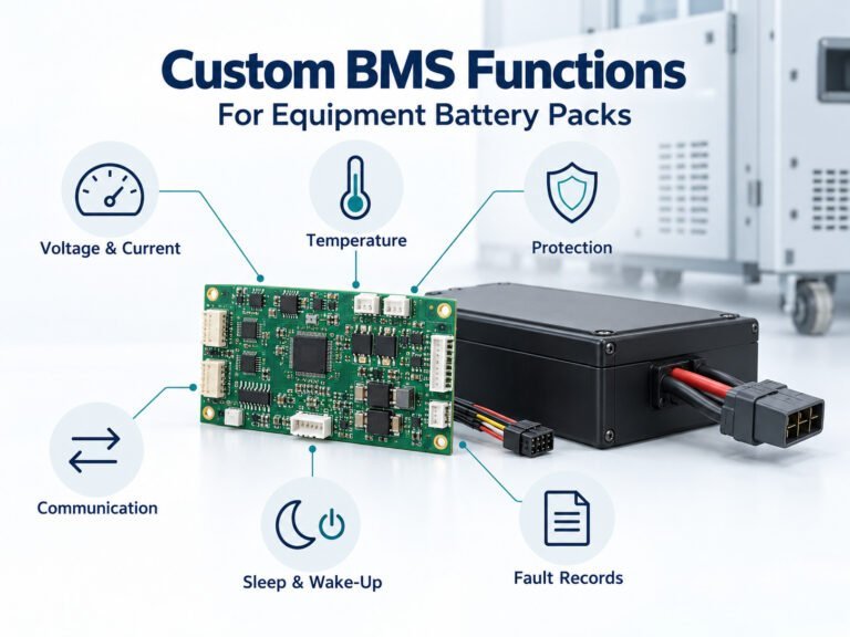
A BMS can monitor and control multiple parameters depending on the battery architecture and application.
代表的な機能には、次のようなものがあります:
- 過充電保護
- 過放電保護
- 過電流保護
- 短絡保護
- 過熱保護
- 低温保護
- 細胞電位のモニタリング
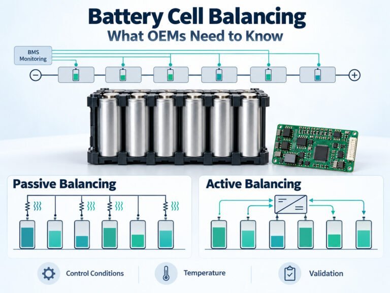
- セルバランシング
- 充電状態の推定
- State-of-health monitoring
- Charge and discharge control
- 故障検出
- データ通信
For smart industrial equipment, additional communication interfaces may be required, such as:
- CAN
- SMBus
- UART
- RS485
- RS232
- ブルートゥース
The BMS should be designed around the equipment rather than selected as an isolated component.
For a simple portable product, basic protection functions may be sufficient.
For an AGV, AMR, industrial robot, or fleet-operated vehicle, the battery may need to communicate voltage, current, temperature, SOC, alarms, and other operating information to the equipment controller.
BMS Parameter Configuration
BMS protection thresholds should be evaluated together with the selected cell chemistry and equipment requirements.
パラメータには、次のようなものがあります:
- Cell overvoltage threshold
- Cell undervoltage threshold
- Charge overcurrent threshold
- Discharge overcurrent threshold
- Short-circuit response
- 高温保護
- 低温時の充電保護
- Balancing conditions
- Recovery conditions
Incorrect parameter configuration can result in premature protection or insufficient battery protection.
Therefore, BMS development should be validated using both laboratory testing and actual equipment testing.
6. Develop the Mechanical Structure
Electrical design is only one part of a custom battery pack.
The battery must physically fit inside the customer’s equipment and remain secure during operation.
Mechanical design may include:
- 細胞の配列
- バッテリー収納ケース
- セルホルダー
- BMSの取り付け
- ケーブルの配線
- Connector positioning
- 取り付け位置
- Handle or pull-out mechanism
- Sealing structure
- 断熱
- Shock protection
- 振動対策
- 熱管理
Space constraints are particularly important in portable and embedded battery applications.
For example, a medical device may require a compact battery with a dedicated insertion and removal mechanism.
An industrial robot may require a battery that can be quickly replaced during operation.
An outdoor device may require an enclosure designed to resist dust and water ingress.
The mechanical design therefore needs to be developed together with the electrical architecture.
7. Consider Thermal Management
Battery temperature affects performance, charging behavior, safety, and service life.
Thermal analysis should consider:
- 連続放電電流
- ピーク電流
- 細胞内抵抗
- 周囲温度
- 筐体設計
- 放熱
- 充電電流
- Operating duty cycle
High-current applications may generate significant heat during operation.
If heat cannot be effectively dissipated, battery temperature can increase and affect performance.
Depending on the application, thermal management may involve:
- セル間隔
- Heat-conductive materials
- Thermal interface materials
- 換気
- Heat sinks
- 筐体設計
- 温度センサー
- Software-based current limitation
The appropriate solution depends on the battery size and application.
8. Design Electrical Connections and Protection Components
The internal electrical connection system also affects battery performance.
Depending on the design, battery packs may use:
- Nickel strip welding
- レーザー溶接
- バスバー
- Copper connections
- Flexible connections
- Wire harnesses
- ヒューズ
- リレー
- コネクタ
For high-current battery packs, resistance within the electrical path can generate heat and cause voltage drop.
The engineering team therefore needs to evaluate the complete current path:
Cell → connection → fuse → BMS → wire → connector → equipment
Every component should be selected according to the required current, voltage, temperature, mechanical environment, and expected service life.
9. Build the Engineering Prototype
After the electrical, mechanical, and BMS design is approved, the project moves to prototype production.
A typical prototype process includes:
Engineering design → BOM confirmation → cell preparation → cell sorting → BMS preparation → structural parts → battery assembly → electrical testing
The prototype is used to verify whether the proposed design works in a real product environment.
Important prototype checks include:
- 寸法
- 重量
- 電圧
- 定員
- 内部抵抗
- Charge performance
- 放電性能
- 気温の上昇
- BMS保護
- コミュニケーション
- Connector compatibility
- 機器の設置
- Mechanical stability
Prototype development is also an opportunity to identify issues before committing to larger production volumes.
10. Conduct Battery Pack Testing
Battery testing should be based on the actual application requirements.
電気試験
Common tests include:
- 開回路電圧
- 定員
- 内部抵抗
- 充放電性能
- 連続排出
- Peak discharge
- 充電特性
- 待機電流
BMS Protection Testing
Protection functions can be verified through controlled tests for:
- オーバーチャージ
- 過放電
- 過電流
- ショート
- 過熱
- Low-temperature conditions
- Cell voltage abnormalities
Environmental and Mechanical Testing
Depending on the application, validation may include:
- 高温試験
- 低温試験
- 温度サイクル試験
- 振動試験
- 機械的衝撃
- 落下試験
- Water ingress testing
- Dust protection testing
- Long-duration cycling
For industrial equipment and outdoor robots, vibration and environmental testing can be particularly important because the battery may experience repeated mechanical stress.
11. Validate the Battery on the Final Equipment
Laboratory testing is essential, but it cannot completely replace testing on the final device.
The battery should be installed into the target equipment and evaluated under representative operating conditions.
For example, an AGV duty cycle may include:
Start → accelerate → move → decelerate → stop → turn → carry load → restart
This dynamic load profile is different from a simple constant-current laboratory test.
Equipment-level testing can evaluate:
- Startup performance
- 実行時間
- ピーク出力
- Motor acceleration
- 気温の上昇
- SOCの精度
- BMS通信
- Low-battery behavior
- 充電特性
- Long-duration operation
The purpose is to confirm that the battery performs as an integrated component of the complete system.
12. Confirm Certification and Market Requirements
Certification and transportation requirements should be considered early in the project.
The requirements depend on the battery chemistry, application, product category, and destination market.
Depending on the project, relevant standards and requirements may include:
- UN38.3
- IEC 62133-2
- UL規格
- CE関連の要件
- RoHS
- PSE
- KC
- Applicable EU battery requirements
The exact certification path should be confirmed according to the final product and target market.
Certification should not be treated as an afterthought.
A change to the cell, BMS, enclosure, protection circuit, or electrical architecture may affect the certification process.
Early planning can therefore reduce redesign risk.
13. Move From Prototype to Pilot Production
Once the prototype has passed engineering and equipment-level validation, the next stage is pilot production.
Pilot production is different from producing a few engineering samples.
The purpose is to determine whether the product can be manufactured consistently using the intended production process.
The pilot run can validate:
- BOM stability
- Assembly procedures
- Welding parameters
- BMSプログラミング
- Test procedures
- Production fixtures
- Work instructions
- Operator processes
- 製品の一貫性
- パッケージ
- 生産効率
This stage helps answer an important question:
Can the engineering design be reproduced reliably at production scale?
14. Establish Production and Quality Standards
Before mass production, technical documents should be finalized.
A typical production documentation package may include:
- Bill of Materials
- Product specification
- 細胞の分化決定
- BMS仕様書
- PCB revision
- Mechanical drawings
- Wiring diagrams
- Standard Operating Procedures
- Quality inspection standards
- Test specifications
- Packaging specifications
- Outgoing inspection standards
Critical process parameters should also be documented.
For example, a welded battery pack may require controlled welding energy, welding time, weld-point quantity, and weld strength.
Standardized production parameters help reduce variation between production batches.
15. Mass Production
Once the design and pilot production have been validated, the project can enter mass production.
A typical battery pack production process may include:
IQC → Cell sorting → Cell matching → Pack assembly → BMS installation → Welding → Wiring → Structural assembly → Programming → Electrical testing → Aging → Final inspection → Packaging → OQC → Shipment
Quality control should be applied throughout the process rather than only at the final inspection stage.
Important control points may include:
- 入荷セル検査
- 細胞電位
- セル容量
- 内部抵抗
- セルの照合
- 溶接品質
- BMS function
- 断熱
- パック電圧
- 定員
- 充電性能
- 保護機能
- 外観
- Labeling
- パッケージ
16. Aging and Final Inspection
Battery aging can help identify abnormal behavior before shipment.
Depending on the product design, the aging process may monitor:
- 電圧安定性
- Current behavior
- 温度
- BMSの動作
- 自己放電
- Charging and discharging behavior
Final inspection confirms that the completed battery matches the approved specification.
For OEM customers, production records and inspection data can also support product traceability and quality management.
17. Production Traceability and Change Management
Long-term OEM projects require more than stable production equipment.
They also require controlled product changes.
A battery pack may contain dozens of components, and changing one component can affect the overall product.
Potential changes include:
- 電池セルモデル
- BMS IC
- MOSFET
- コネクタ
- Wire
- ヒューズ
- Enclosure material
- Structural component
- Firmware
- パッケージ
These changes should be evaluated through an engineering change process before implementation.
For long-term programs, traceability can help manufacturers identify the production batch, component lot, test records, and relevant manufacturing information associated with each battery pack.
This becomes particularly valuable when products are shipped to multiple markets or used in industrial applications.
Custom Battery Pack OEM/ODM Development Flow
The complete development process can be summarized as:
Customer Requirements
↓
Application and Load Analysis
↓
Voltage and Capacity Calculation
↓
細胞の選択
↓
BMS Design
↓
機械設計
↓
Electrical and Thermal Design
↓
Engineering Prototype
↓
Laboratory Testing
↓
Equipment-Level Validation
↓
Certification and Compliance
↓
Pilot Production
↓
Production Validation
↓
量産
↓
Quality Control and Traceability
This process provides a structured path from an initial battery concept to a production-ready battery pack.
What Information Should You Provide to a Battery Pack Manufacturer?
The more complete the initial specification, the more efficiently the engineering team can evaluate the project.
For a custom battery pack inquiry, customers should ideally provide:
電気的要件
- 公称電圧
- 動作電圧範囲
- 定員
- 連続電流
- ピーク電流
- ピークの持続時間
- Power consumption
機械的要件
- Maximum length
- Maximum width
- Maximum height
- Maximum weight
- 取り付け方法
- コネクタの位置
- Battery replacement method
環境要件
- 動作温度
- 充電温度
- 保存温度
- 湿度
- 振動
- 衝撃
- Waterproof requirements
Functional Requirements
- BMS通信
- SOC display
- Battery indicator
- Heating or cooling
- 急速充電
- Hot swapping
- データロギング
Commercial Requirements
- Prototype quantity
- Target annual volume
- ターゲット市場
- Required certification
- Expected product lifetime
- Target development schedule
Providing these details allows an OEM/ODM battery manufacturer to evaluate the project from both engineering and manufacturing perspectives.
How to Choose a Custom Battery Pack OEM/ODM Manufacturer
Price is only one part of a battery sourcing decision.
A reliable custom battery project requires coordination between several engineering disciplines.
When evaluating a battery pack manufacturer, consider whether the supplier has capabilities in:
細胞の選択
Can the manufacturer recommend cells according to the actual application rather than simply offering a standard battery?
BMS開発
Can the supplier configure or develop BMS hardware, protection parameters, firmware, and communication functions?
Mechanical Engineering
Can the manufacturer develop customized battery dimensions, mounting structures, connectors, housings, and waterproof solutions?
試作開発
Can the supplier move efficiently from technical specifications to engineering samples and pilot production?
テスト
Does the manufacturer have appropriate equipment for capacity, aging, temperature, vibration, waterproofing, and BMS testing?
認証サポート
Can the supplier help identify and prepare the required compliance and transportation documentation for the target market?
Manufacturing
Does the supplier have controlled production processes, quality inspection procedures, cell matching, traceability, and production capacity for long-term OEM programs?
A capable OEM/ODM partner should be able to participate throughout the product lifecycle rather than only assemble battery cells after the design is completed.
Why OEM and ODM Battery Development Can Reduce Project Risk
OEM and ODM cooperation can be useful when the customer does not want to develop every part of the battery internally.
With an OEM model, the customer may already have a defined battery design and require a manufacturing partner to produce it according to approved specifications.
With an ODM model, the battery manufacturer can participate earlier in the development process, including:
Requirements → Electrical design → Cell selection → BMS → Mechanical design → Prototype → Testing → Production
Early engineering involvement can help identify potential problems before the product reaches mass production.
For example, a manufacturer may identify that the required peak current is too high for the selected cell configuration, that the proposed battery dimensions leave insufficient space for the BMS, or that the selected connector is not suitable for the expected current.
Finding these issues during the engineering stage is generally easier than correcting them after production has started.
Common Mistakes in Custom Battery Pack Projects
Choosing a Cell Based Only on Capacity
A higher-capacity cell does not automatically make a better battery.
Discharge capability, internal resistance, dimensions, temperature characteristics, cycle life, and supply stability also matter.
Designing the Battery Before Understanding the Load
The battery must be designed according to the equipment’s actual load profile.
Ignoring startup and peak current can cause unexpected BMS protection or voltage drop.
Treating the BMS as a Standard Component
Different applications can require different BMS functions and communication protocols.
BMS configuration should be matched to the cell chemistry and equipment.
Ignoring Mechanical Constraints
A battery that works electrically but does not fit the equipment is not a finished solution.
Mechanical design should begin early in the development process.
Testing Only the Battery
A battery can pass a laboratory test but still perform differently when installed in the final device.
Equipment-level validation is important for applications with dynamic loads.
Waiting Until the End to Consider Certification
Certification and regulatory requirements can influence battery architecture.
They should be considered before the design is finalized.
FAQ About Custom Battery Pack Design
カスタムバッテリーパックの開発にはどれくらい時間がかかりますか?
The development timeline depends on the battery chemistry, electrical architecture, BMS requirements, mechanical complexity, prototype requirements, testing, certification, and production volume.
A relatively straightforward battery pack may move through development faster than a complex industrial or medical battery requiring customized BMS communication and extensive validation.
Can I specify the battery cell brand or model?
Yes. A customer can specify a preferred cell, but the manufacturer should evaluate its electrical characteristics, dimensions, supply stability, compatibility with the BMS, and suitability for the intended application.
BMSはカスタマイズできますか?
Yes. BMS functions can be configured or developed according to the battery chemistry, current requirements, protection strategy, communication interface, and equipment controller.
Can you design the battery pack enclosure?
For ODM projects, battery manufacturers may provide mechanical engineering support for dimensions, housing, mounting structures, connectors, sealing, and internal component arrangement.
Can a battery pack be designed for outdoor equipment?
Yes. Outdoor battery packs can be designed around the required temperature range, vibration conditions, water and dust exposure, mechanical protection, and charging environment.
The appropriate IP protection level should be determined according to the actual application.
Can you provide prototype samples before mass production?
A typical OEM/ODM development process includes engineering prototypes followed by validation and, when required, pilot production before mass production.
What is the difference between OEM and ODM battery packs?
OEM generally means manufacturing according to the customer’s existing design or specification.
ODM involves greater participation from the battery manufacturer in product development, such as electrical architecture, BMS, mechanical design, cell selection, prototyping, testing, and production engineering.
結論
Custom battery pack development is a complete engineering process rather than a simple assembly operation.
A successful project typically moves through several connected stages:
Requirements → Electrical Design → Cell Selection → BMS → Mechanical Design → Prototype → Testing → Certification → Pilot Production → Mass Production
Each stage contributes to the safety, performance, reliability, manufacturability, and long-term consistency of the final battery.
For companies developing industrial robots, AGVs, AMRs, medical equipment, portable devices, power tools, e-bikes, drones, golf carts, UPS systems, or energy storage products, working with an experienced battery pack OEM/ODM manufacturer can simplify the development process and reduce the gap between engineering design and mass production.
Dongguan Yizhan Electronics Technology Co., Ltd. provides customized lithium battery pack solutions for different equipment and application requirements, with capabilities covering cell selection, battery pack design, BMS development, prototype production, testing, certification support, OEM/ODM manufacturing, and mass production.
The right battery specification starts with the application. The right manufacturing process turns that specification into a repeatable product.
 English
  Chinese
  Japanese
  German
  French
  Korean
