
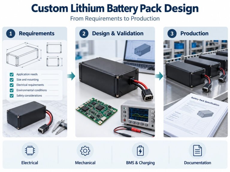
Custom lithium battery pack design begins with the equipment’s operating requirements. Voltage and capacity are part of the specification, but the design must also address current demand, installation, charging, protection and communication.
The development process connects these requirements to a defined construction, validation plan and production document set.
This guide explains the stages OEM teams should document when developing a battery pack for equipment.

1. Define the Application
Describe what the equipment does and how it will be used.
Include:
- Equipment function.
- Operating schedule.
- Load conditions.
- Indoor or outdoor installation.
- Charging opportunities.
- Handling and maintenance.
- Storage periods.
- Destination markets.
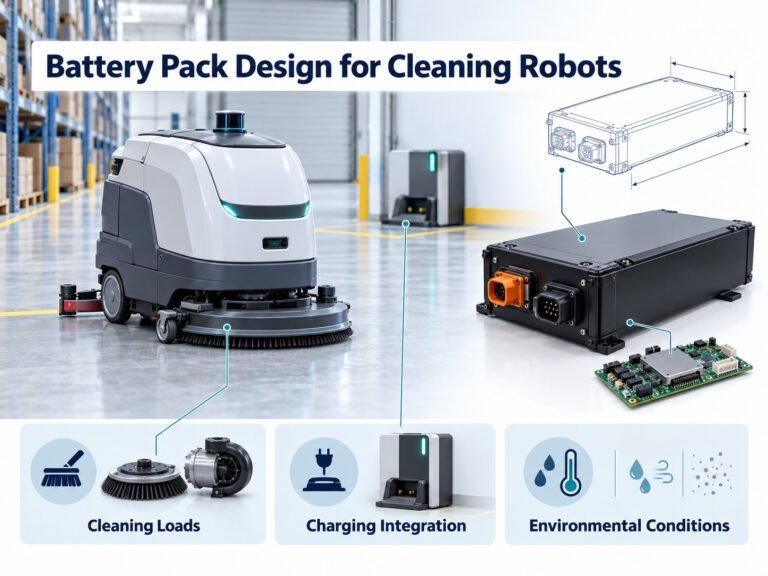
A battery for a portable instrument has different requirements from one used in a cleaning robot or agricultural machine.
Use application-specific information rather than selecting a pack from its nominal ratings alone.
2. Separate Requirements From Assumptions
During development, some values are confirmed while others remain estimates.
Record the status of each requirement.
| Status | Meaning |
|---|---|
| Measured | Supported by recorded test data |
| Proposed | Awaiting review |
| Approved | Accepted for the design |
| Open | Requires a decision |
Identify the owner of each open item.
If runtime, installation space or charging time has not been confirmed, state that explicitly. An assumption should not become a production requirement without review.
3. Establish the Electrical Load Profile
Measure battery-side voltage and current during:
- Startup.
- Normal operation.
- Motor or actuator activity.
- Data processing.
- Standby.
- Shutdown.
For transient events, record current magnitude, duration and repetition.
Document the equipment configuration, payload, software and environmental conditions.
Component nameplate ratings do not describe the complete equipment’s consumption throughout a task.
4. Specify Voltage and Energy
Voltage Range
Define:
- Nominal voltage.
- Full-charge voltage.
- Normal discharge endpoint.
- Equipment input limits.
- Permitted voltage behavior during load changes.
The cell chemistry and series configuration determine the battery voltage characteristics.
Check the controller, converters, display and accessories across the approved range.
Task Energy
Calculate energy for each operating stage:
Energy (Wh) = average battery-side power (W) × duration (h)
Then account for the operating window, temperature, reserve requirements and battery condition at the service endpoint.
Nominal battery energy can be estimated as:
Nominal energy (Wh) = nominal voltage (V) × capacity (Ah)
Nominal energy does not establish usable energy in every application.
5. Define Current Requirements
Specify continuous and transient current separately.
The current path includes:
- Cells.
- Interconnections.
- Protective devices.
- BMS switching components.
- Cables.
- Connectors.
Review startup, repeated load events and fault conditions.
A cell’s current rating does not establish the rating of the assembled pack. Capacity alone does not establish current capability.
6. Select Cells
Cell selection should address the approved electrical and mechanical requirements.
Document:
- Chemistry.
- Manufacturer and model.
- Capacity and measurement conditions.
- Charge and discharge limits.
- Temperature limits.
- Dimensions.
- Supporting technical records.
Review cycle-life statements with their test conditions and endpoints. Do not convert a cell cycle count into a guaranteed equipment service period.
Identify whether substitutions are permitted and how they will be approved.
7. Develop the Mechanical Design
Provide an installation drawing or equipment model.
Define:
- Battery envelope and tolerances.
- Mounting points.
- Installation orientation.
- Mass limit.
- Connector locations.
- Cable routing.
- Removal path.
- Service access.
The pack also needs space for insulation, interconnections, electronics and structural parts.
For removable batteries, document handling, insertion, locking and removal. Verify the intended procedure using the equipment assembly.
8. Specify the BMS
Select or develop the battery management system according to the required functions.
These may include:
- Voltage monitoring.
- Current measurement.
- Temperature sensing.
- Charge and discharge protection.
- Balancing.
- State-of-charge reporting.
- Sleep and wake-up.
- Fault records.
- Communication.
Define thresholds, delays, actions and recovery behavior.
Protection settings must follow the approved cell, component and system limits. Do not adjust protection merely to accommodate an unverified load.
9. Define Equipment Interfaces
Specify power and signal connections.
Record:
- Connector part numbers.
- Mating components.
- Polarity.
- Pin assignments.
- Cable specifications.
- Connection sequence.
- Signal functions.
Where communication is required, also define messages, units, scaling, timing, timeouts and firmware versions.
An interface label such as CAN or RS485 does not establish compatibility with the host protocol.
10. Coordinate Charging
Charging requirements belong in the battery specification.
Define:
- Approved charger or charging-source requirements.
- Voltage and current.
- Temperature restrictions.
- Termination behavior.
- Connector and polarity.
- Communication.
- Fault response.
If the equipment operates during charging, document the power path and verify that mode.
For automatic docking, include alignment, contact engagement and charging permission.
Do not calculate charging time solely by dividing capacity by charger current.
11. Review Environmental and Thermal Conditions
Describe exposure during operation, charging, transport and storage.
Consider:
- Temperature.
- Moisture and condensation.
- Dust.
- Cleaning agents.
- Vibration.
- Mechanical shock.
- Sunlight.
- Adjacent heat sources.
Measure temperatures in the intended installation.
If an ingress protection rating is required, identify the assembly and test conditions. A seal or enclosure material alone does not establish the rating.
12. Plan Documentation and Assessment
Identify applicable product, equipment and transport requirements before design release.
Agree on:
- Standards and editions.
- Assessment object.
- Model coverage.
- Required samples.
- Supporting documents.
- Reports or certificates.
- Responsibilities.
Cell documents do not automatically cover a battery pack. Battery assessment does not automatically cover the complete equipment.
The required scope depends on the application and destination market.
13. Build and Record Prototypes
Identify each sample by construction revision.
Record:
- Cell model.
- BMS hardware.
- Firmware and settings.
- Enclosure.
- Wiring.
- Connectors.
- Deviations from the proposed design.
Define each sample’s purpose, such as installation review, functional testing or environmental assessment.
Do not treat an undocumented sample as the production reference.
14. Validate the Design
Set acceptance criteria before testing.
| Test Area | Verification |
|---|---|
| Electrical operation | Voltage, current and startup behavior |
| Task energy | Completion of the defined operating sequence |
| Charging | Profile, termination and fault handling |
| Protection | Trigger, action and recovery |
| Communication | Interpretation, timing and data loss |
| Thermal behavior | Cell and component temperatures |
| Mechanical integration | Mounting, wiring and handling |
| Environmental exposure | Specified project conditions |
| Shutdown | Controlled power-down and recovery |
Record test conditions and results.
If the design changes after testing, review whether the existing evidence remains applicable.
15. Prepare Production Documents
The approved document set should define what will be built.
| Document | Content |
|---|---|
| Product specification | Ratings, limits and operating conditions |
| Drawings | Dimensions, mounting and interfaces |
| Bill of materials | Approved components |
| BMS configuration | Hardware, firmware and settings |
| Test plan | Procedures and acceptance criteria |
| Label drawing | Identification and traceability |
| Instructions | Installation, charging, storage and handling |
| Packaging specification | Restraint, protection and supplied items |
Assign identifiers and revisions. Resolve conflicts before production release.
16. Establish Production Checks
Design validation and routine production checks have different purposes.
Define the checks required for manufactured units, which may include:
- Visual inspection.
- Polarity.
- Voltage.
- Configuration verification.
- Communication.
- Selected protection functions.
- Specified insulation measurements.
- Functional or capacity checks.
Document sampling, equipment and acceptance criteria.
Destructive testing requires a separate sample and evaluation plan.
17. Control Changes and Traceability
Review proposed changes to cells, electronics, firmware, settings, interfaces and construction.
Record:
- The change.
- Its reason.
- Affected requirements.
- Required verification.
- Approval.
- Implementation batch.
Link product identification to manufacturing and inspection records.
A serial number supports traceability when the associated records are maintained.
OEM Project Checklist
Before approving production, confirm:
- Application and operating profile.
- Electrical requirements.
- Cell model and configuration.
- Mechanical interfaces.
- BMS functions and settings.
- Charging arrangement.
- Communication.
- Environmental conditions.
- Validation results.
- Required assessment documents.
- Production checks.
- Labels and instructions.
- Change-control responsibilities.
Record unresolved items and their disposition.
Frequently Asked Questions
Can a Custom Pack Use an Existing Enclosure?
Yes, if the enclosure supports the required construction, installation and operating conditions.
Can Capacity Be Changed Without Other Design Changes?
That requires review. Cell selection and configuration can affect current, temperature, mass and document coverage.
Does a Working Prototype Establish Production Readiness?
No. Production also requires approved documents, acceptance criteria and process controls.
Can One Battery Serve Several Equipment Models?
Possibly, when compatibility is defined and validated for each intended combination.
What Should Be Supplied With the Battery?
Agree on instructions, specifications, interface documents, inspection records and applicable reports as part of the project scope.
From Requirements to Production
Begin with the equipment’s measured demands and installation conditions.
Convert those inputs into approved requirements, verify the proposed design and release production against controlled documents. Manage subsequent changes through the agreed review process.

 English
 Chinese
 Japanese
 German
 French
 Korean

